Rotating paper conveying device

A paper feeding device and paper feeding technology, applied in the field of machinery, can solve the problems of low working efficiency of the whole die-cutting machine, low paper feeding efficiency of the paper feeding part of the die-cutting machine, etc.

Inactive Publication Date: 2018-07-24
BEIJING INSTITUTE OF GRAPHIC COMMUNICATION +1
View PDF3 Cites 1 Cited by
  • Summary
  • Abstract
  • Description
  • Claims
  • Application Information

AI Technical Summary

Problems solved by technology

[0003] In view of this, the purpose of this application is to propose a rotary paper feeding device to solve the problem of low working efficiency of the die-cutting machine caused by the low paper feeding efficiency of the paper feeding part of the die-cutting machine

Method used


Image

  • Rotating paper conveying device
  • Rotating paper conveying device

Examples


Embodiment Construction

[0019] The application will be further described in detail below in conjunction with the accompanying drawings and embodiments. It should be understood that the specific embodiments described here are only used to explain related inventions, rather than to limit the invention. It should also be noted that, for the convenience of description, only the parts related to the related invention are shown in the drawings.

[0020] It should be noted that, in the case of no conflict, the embodiments in the present application and the features in the embodiments can be combined with each other. The present application will be described in detail below with reference to the accompanying drawings and embodiments.

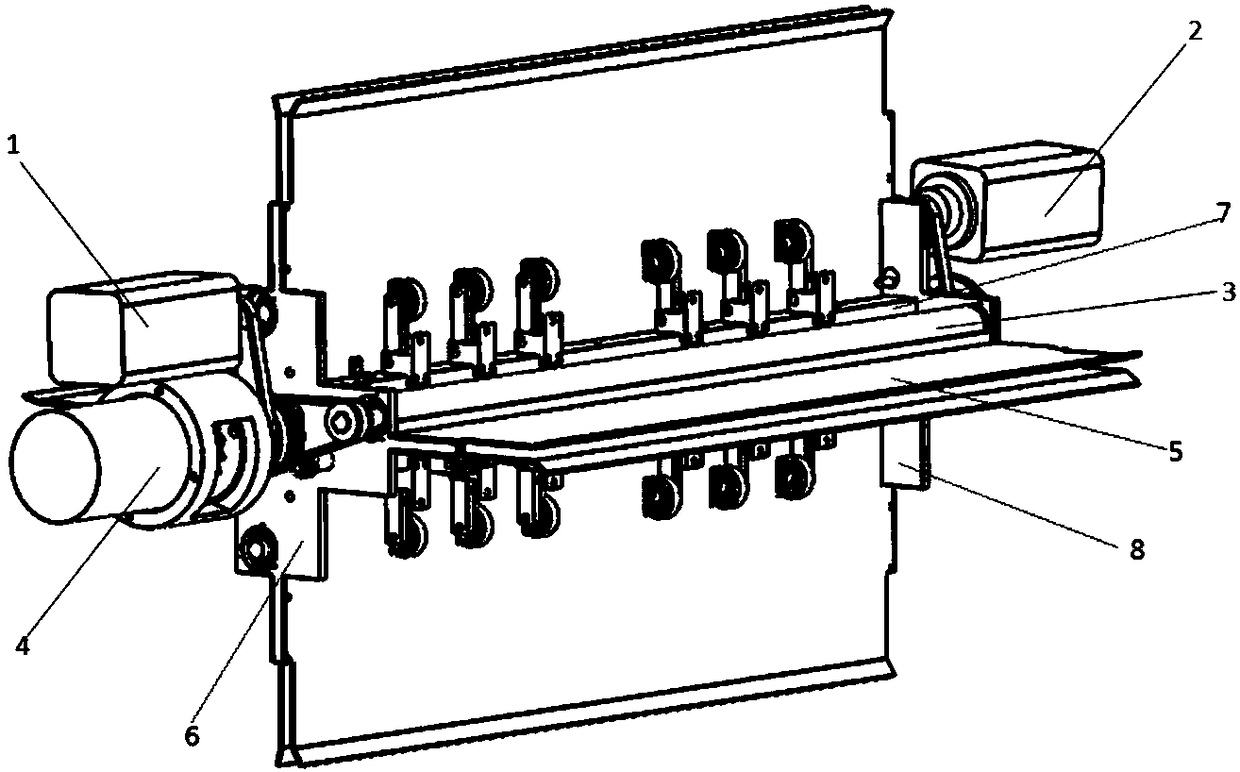
[0021] Such as figure 1 Shown is a schematic diagram of the overall structure of the rotary paper feeding device in Embodiment 1 of the present application. From figure 1 It can be seen from the figure that the rotary paper feeding device in this embodiment includes: a hol...


PUM


Abstract

The embodiment of the invention discloses a rotating paper conveying device. The device comprises a rotating beam, a fixing plate and a paper conveying channel, wherein the rotating beam is of a hollow columnar structure, and four long-strip-shaped groove holes which are formed in the outer side wall are formed in the side wall of the rotating beam in the axial direction; the paper conveying channel comprises a paper inlet channel and a paper outlet channel, the fixing plate is arranged at the two ends of the rotating beam, and the paper inlet channel is arranged perpendicular to the paper outlet channel; the paper outlet of the paper inlet channel and the paper inlet of the paper discharging channel of the same paper conveying channel correspondingly communicates with two opposite grooveholes in the side wall of the rotating beam; and the side edge of the paper conveying channel is connected with the fixing plate. Paper conveying is switched between the paper conveying channels, thepaper conveying efficiency is improved; meanwhile, a star conveying mechanism with a synchronous belt is adopted, and the problem that a traditional star conveying mechanism is limited by a conveyingdistance is solved; and meanwhile, the load of the driving medium belt wheel is balanced, so that transmission loss is reduced.

Description

technical field [0001] The present application relates to the field of mechanical technology, in particular to a rotary paper feeding device. Background technique [0002] Most of the paper delivery mechanisms currently used in the paper delivery section of the die-cutting machine place the whole stack of paper horizontally on the paper delivery platform, and pass the paper forward through the suction nozzle (the paper moves forward in the horizontal direction). However, with the acceleration of the die-cutting speed of the die-cutting machine, the paper-feeding speed of the paper-feeding mechanism of the paper-feeding part of the die-cutting machine also needs to be increased accordingly. Contents of the invention [0003] In view of this, the purpose of this application is to propose a rotary paper feeding device to solve the problem of low working efficiency of the die-cutting machine caused by the low paper feeding efficiency of the paper feeding part of the die-cuttin...

Claims


Application Information

Patent Timeline
Patent Type & Authority Applications(China)
IPC IPC(8): B65H5/06
CPCB65H5/068B65H2701/1131
Inventor 房瑞明关召辉鲁楠王佳琪韩雪
Owner BEIJING INSTITUTE OF GRAPHIC COMMUNICATION
Why Eureka
Try Eureka