
Diversion tunnel blockage structure and method based on karst landform

A diversion tunnel and karst technology, applied in water conservancy projects, sea area projects, hydroelectric power stations, etc., can solve problems such as narrow construction surfaces and difficult sealing, and achieve the effects of high safety, low construction cost, and short construction period

Pending Publication Date: 2018-07-24
中国能源建设集团广西水电工程局有限公司 +1
View PDF4 Cites 3 Cited by
  • Summary
  • Abstract
  • Description
  • Claims
  • Application Information

AI Technical Summary

Problems solved by technology

The water in the diversion tunnel is deep and fast, the construction surface is narrow, and there are major safety hazards in the plugging. At the same time, there are many construction problems such as material transportation, temporary drainage, concrete pouring, and the stability of the plug structure. The plugging is extremely difficult.

Method used


Image

  • Diversion tunnel blockage structure and method based on karst landform
  • Diversion tunnel blockage structure and method based on karst landform
  • Diversion tunnel blockage structure and method based on karst landform

Examples


Embodiment 1

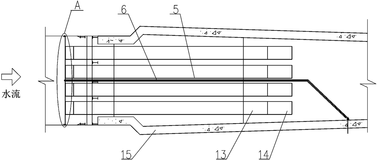
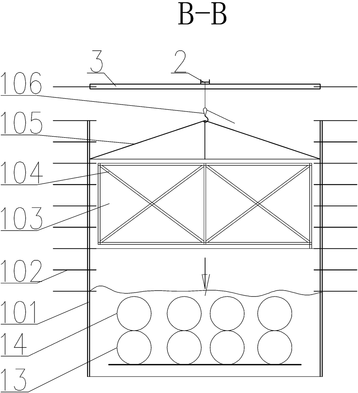
[0041] see Figure 1-8 , based on the diversion tunnel plugging structure of karst landform, the first section of temporary plug 7, the second section of temporary plug 9 and the permanent plug 10 are sequentially arranged inside the concrete lining 15 of the original diversion tunnel along the water flow direction; A water-retaining steel gate 1 is installed upstream of the first section of temporary plug 7, and behind the water-retaining steel gate 1, a stacking beam door 4 is installed. The bottom of the concrete lining 15 is provided with a bottom drainage steel pipe 14 and a top drainage steel pipe 13. The two layers of drainage steel pipes are stacked and arranged. A first disc valve 17 is installed at the water outlet of the top drainage steel pipe 13. There are two second butterfly valves 18 and third butterfly valves 20 arranged at intervals. By adopting the above diversion tunnel sealing structure, the diversion tunnel can be quickly blocked.

[0042] Further, the ...

Embodiment 2

[0051] Any one of the diversion tunnel plugging structures based on karst landforms, it comprises the following steps:

[0052] Step1, Build the construction passage and scaffolding working platform: In order to quickly reach the working surface, the construction road is determined by comprehensively considering factors such as equipment and material transportation, pipeline laying and safe evacuation passages, and a full house of steel pipe supports is erected from the entrance to the temporary plug. The left panel is used as For the transportation channel, steel formwork is laid on the whole line; the right side is covered with bamboo pedals, and the air supply pipe and pump pipe are arranged on the side wall; The first floor is used as a concrete storage platform, and the third floor is used as a reinforcement platform;

[0053] Step2, install the water-retaining steel gate: first, install two door panel columns 101 at the entrance of the diversion tunnel as the guide rail ...


PUM


Abstract

The invention provides a diversion tunnel blockage structure and method based on a karst landform. A first section of temporary plug, a second section of temporary plug and a permanent plug are arranged in a concrete lining of an original diversion tunnel in a water flowing direction in sequence; a water stop steel gate is mounted at the upstream of the first section of temporary plug; a stop loggate is mounted behind the water stop steel gate, and is positioned through cooperation of multiple stand columns; a bottom layer of drainage steel pipe and a top layer of drainage steel pipe are arranged at the bottom of the concrete lining of the original diversion tunnel; the two layers of drainage steel pipes are stacked; a first butterfly valve is mounted in a water outlet of the top layer ofdrainage steel pipe; and a second butterfly valve and a third butterfly valve are mounted in a water outlet of the bottom layer of drainage steel pipe at intervals. Through use of a hydropower station diversion tunnel blockage structure, blockage of the diversion tunnel can be effectively guaranteed, and the dam safety is guaranteed.

Description

technical field [0001] The invention belongs to the technical field of hydraulic engineering construction, and in particular relates to a diversion tunnel plugging structure and method based on karst topography. Background technique [0002] The dam site of the Wanjiakouzi Hydropower Station is located on the Gexiang River in the upper reaches of the main stream of the Beipan River. It is the fourth level of hydropower development on the main stream of the Beipan River. The scale of the project is large (2), mainly for power generation. The main buildings are: rolling Concrete arch dam, dam crest overflow surface hole, energy dissipation pad pond, dam body flushing sand hole, water diversion system, ground powerhouse and switch station, etc. [0003] The normal storage level of the reservoir is 1450 m, the dam crest elevation is 1452.50 m, and the maximum dam height is 167.5 m. It is the highest RCC hyperbolic arch dam currently under construction. ×90MW), the annual averag...

Claims


Application Information

Patent Timeline
Patent Type & Authority Applications(China)
IPC IPC(8): E02B9/02E02B3/16
CPCE02B3/16E02B9/02Y02E10/20
Inventor 卢山龙利秋高宇盘新军黄树鹏罗雄兵班辉叶纯信蒙飞花
Owner 中国能源建设集团广西水电工程局有限公司
Learn More