A double-layer vortex secondary air system for a garbage incinerator

A waste incinerator and secondary air technology, applied in incinerators, combustion types, combustion equipment, etc., can solve the problems of multi-pollutants, poor regulation performance, poor flue gas stirring effect, etc., to improve combustion efficiency, CO concentration The effect of reducing and prolonging residence time

Inactive Publication Date: 2019-08-23
NORTHERN HEAVY IND GRP CO LTD
View PDF6 Cites 2 Cited by
  • Summary
  • Abstract
  • Description
  • Claims
  • Application Information

AI Technical Summary

Problems solved by technology

However, judging from the effect of operation, the overall technical level of the secondary air still follows the early technological path of foreign countries, which does not adapt to China's national conditions, and it is difficult to achieve stable discharge of pollutants.
In the prior art, the secondary air nozzles are located at the front arch and the rear arch, the nozzles are arranged in a staggered manner, and the wind speed of all the nozzles is the same, which cannot adapt to the unstable calorific value of municipal solid waste, resulting in unstable combustion of waste in the furnace and generating more Emissions of pollutants, especially dioxins
On the other hand, the secondary air has little effect on the flue gas agitation effect in the upper furnace, resulting in poor flue gas agitation effect in the furnace, which cannot meet the flue gas area residence time > 2s stipulated in the "Standards for Pollution Control of Domestic Waste Incineration"
The existing secondary air device has poor adjustment performance, which can no longer meet the needs of ensuring the stable combustion of garbage in the furnace

Method used


Image

  • A double-layer vortex secondary air system for a garbage incinerator
  • A double-layer vortex secondary air system for a garbage incinerator
  • A double-layer vortex secondary air system for a garbage incinerator

Examples


Embodiment Construction

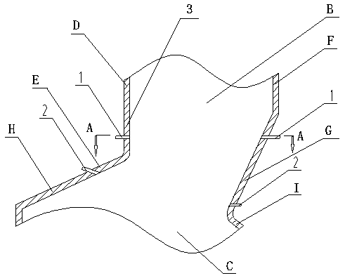
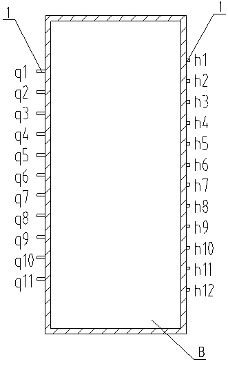
[0013] Referring to the accompanying drawings, a double-layer vortex secondary air system for a garbage incinerator includes an upper vortex secondary air nozzle 1, a lower secondary air nozzle 2, and a garbage incinerator body 3. The upper part of the garbage incinerator body 3 is The upper furnace B, the lower part of the garbage incinerator body 3 is the lower combustion chamber C, the upper layer vortex secondary air nozzle 1 is set at the junction of the front wall section D of the garbage incinerator body 3 and the middle section E of the front wall, and the rear of the garbage incinerator body 3 The upper vortex secondary air nozzle 1 is set at the connection between the wall section F and the rear wall middle section G, the lower secondary air nozzle 2 is set at the connection between the front wall middle section E of the garbage incinerator body 3 and the front wall lower section H, and the garbage incinerator body 3 The lower secondary air nozzle 2 is arranged at the...


PUM


Abstract

A double-layer vortex secondary air system of a garbage incinerator comprises upper layer vortex secondary air nozzles, lower layer secondary air nozzles and a garbage incinerator body, wherein the upper portion of the garbage incinerator body is provided with an upper furnace B, and the lower portion of the garbage incinerator body is provided with a lower combustion chamber C. One of the upper layer vortex secondary air nozzles is arranged at the junction of the upper section D of the front wall and the middle section E of the front wall of the garbage incinerator body, and the other one ofthe upper layer vortex secondary air nozzles is arranged at the junction of the upper section F of the rear wall and the middle section G of the rear wall of the garbage incinerator body. One of the lower layer secondary air nozzles is arranged at the junction of the middle section E of the front wall and the lower section H of the front wall of the garbage incinerator body, and the other one of the lower layer secondary air nozzles is arranged at the junction of the middle section G of the rear wall and the lower section I of the rear wall of the garbage incinerator body. According to the double-layer vortex secondary air system of the garbage incinerator, the horizontal vortex combustion technology is adopted for upper layer vortex secondary air, flue gas is in a spirally-rising state, the concentration of co is significantly reduced, and the combustion is more sufficient; the upper layer vortex secondary air constitutes a symmetric double-vortex region, and the combustion efficiencyis improved; and the double-layer vortex secondary air system of the garbage incinerator is used in the technical field of garbage incineration equipment of a large-scale power plant.

Description

technical field [0001] The invention relates to a double-layer vortex secondary air system of a garbage incinerator in the technical field of garbage incineration equipment in large power plants. Background technique [0002] At present, large-scale domestic waste incineration power plants have been in operation for a period of time in my country, and the technical level of their equipment has been continuously improved no matter whether they are imported from abroad or independently developed. The researchers focused on improving the technical level of mechanical grate furnaces, which played a certain role in improving the combustion efficiency. However, judging from the effect of operation, the overall technical level of secondary air still follows the early technological path abroad, which does not adapt to China's national conditions, and it is difficult to achieve stable discharge of pollutants. In the prior art, the secondary air nozzles are located at the front arch ...

Claims


Application Information

Patent Timeline
Patent Type & Authority Patents(China)
IPC IPC(8): F23G5/44F23L9/00
Inventor 霍光赵绪平李志波李镭单东升张伟李宣李炜炜王中原苏小华常亮周伟王莹商迪侯彬
Owner NORTHERN HEAVY IND GRP CO LTD
Why Eureka
Try Eureka