Ice and snow removing robot for high voltage cable

A technology of high-voltage cables and robots, which is applied to the installation of cables, electrical components, overhead installations, etc., and can solve problems such as the inability to clean ice and snow on high-voltage cables

Active Publication Date: 2018-07-24
JIANGMEN POWER SUPPLY BUREAU OF GUANGDONG POWER GRID
View PDF4 Cites 5 Cited by
  • Summary
  • Abstract
  • Description
  • Claims
  • Application Information

AI Technical Summary

Problems solved by technology

But the invention cannot clean ice and snow on high-voltage cables, and it cannot automatically travel along the cable to clean

Method used


Image

  • Ice and snow removing robot for high voltage cable
  • Ice and snow removing robot for high voltage cable
  • Ice and snow removing robot for high voltage cable

Examples


specific Embodiment approach 1

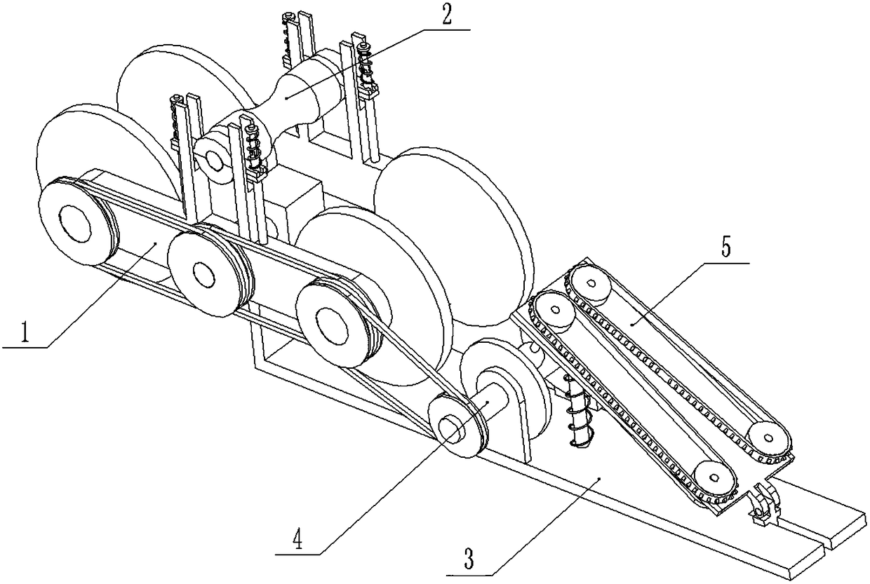
[0029] Combine below Figure 1-10 Describe this embodiment, a high-voltage cable ice and snow removal robot, including a cable lower propulsion device 1, an upper clamping device 2, a cleaning frame 3, a driven grinding disc assembly 4 and a cleaner 5, and the upper clamping device 2 is fixedly connected to At the upper end of the cable propulsion device 1, the cleaning frame 3 is fixedly connected to the lower end of the cable propulsion device 1, the driven grinding disc assembly 4 is rotatably connected to the cleaning frame 3, and the right end of the cleaner 5 slides Hinged on the cleaning frame 3, the left end of the cleaner 5 is slidably connected to the cleaning frame 3, the driven grinding disc assembly 4 is located between the cable lower propulsion device 1 and the cleaner 5, the driven grinding disc assembly 4 is connected with the lower cable propulsion device 1 through a belt transmission, and the driven grinding disc assembly 4 is linked with the cleaner 5; when...

specific Embodiment approach 2

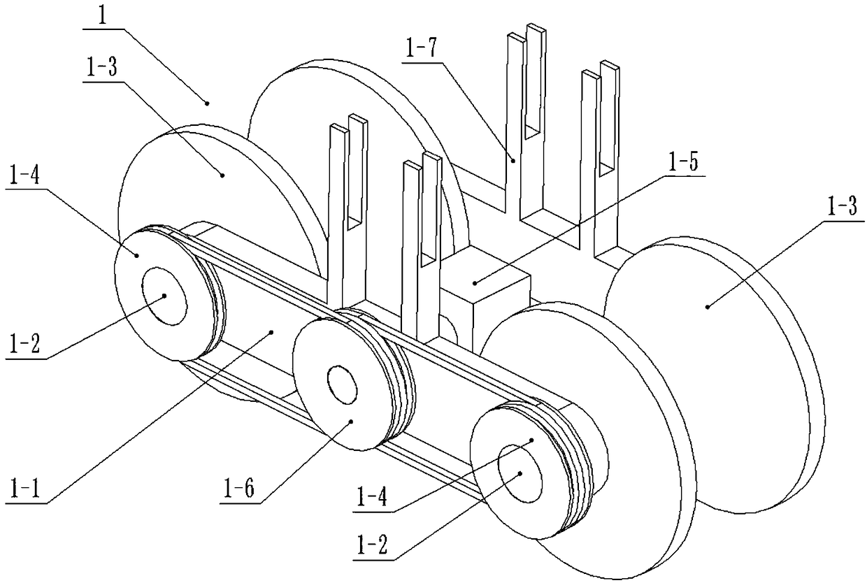
[0030] Combine below Figure 1-10Describe this embodiment, this embodiment will further explain the first embodiment, the cable propulsion device 1 includes a propulsion frame 1-1, two propulsion shafts 1-2, two lower crimping wheels 1-3, two Pulley Ⅰ 1-4, drive motor 1-5, pulley Ⅱ 1-6 and crimping carriage 1-7, the left and right ends of the propulsion frame 1-1 are respectively rotated and connected with a propulsion shaft 1-2, the propulsion shaft 1-2 is fixedly connected with a lower crimping wheel 1-3, the pulley I1-4 is fixedly connected to one end of the propulsion shaft 1-2, and the drive motor 1-5 is fixedly connected to the propulsion frame 1-1 , the pulley II 1-6 is fixedly connected to the transmission shaft of the drive motor 1-5, and the push frame 1-1 is fixedly connected with four crimping carriages 1-7, and the pulley II 1-6 They are respectively connected to the two belt pulleys I1-4 through belt transmission; the two lower crimping wheels 1-3 are driven to ...

specific Embodiment approach 3

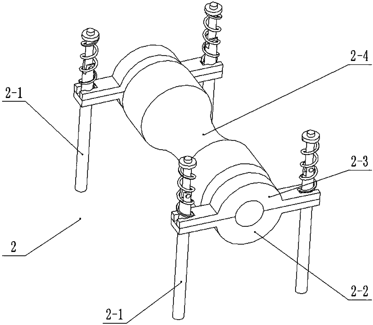
[0031] Combine below Figure 1-10 This embodiment will be described. This embodiment will further describe the second embodiment. The upper clamping device 2 includes a support rod 2-1, two lower shaft frames 2-2, two upper shaft frames 2-3 and an upper pressing Wire wheel 2-4, four support rods 2-1 are set, and the four support rods 2-1 are fixedly connected on the propulsion frame 1-1, and the four support rods 2-1 are connected with the four crimping wires respectively Sliding frame 1-7 is arranged relatively, two support rods 2-1 of the front end are slidingly connected with a lower shaft frame 2-2 and an upper shaft frame 2-3, and the two support rods 2-1 of the rear end are slidingly connected with A lower pedestal 2-2 and an upper pedestal 2-3, the lower pedestal 2-2 and the upper pedestal 2-3 are all slidably connected on the crimping carriage 1-7, the lower pedestal 2 Shaft holes are formed between -2 and the upper shaft frame 2-3, and the upper crimping wheel 2-4 is...


PUM


Abstract

The invention relates to a cleaning device for a high voltage cable, in particular to an ice and snow removing robot for the high voltage cable. The ice and snow removing robot for the high voltage cable includes a cable lower pushing device, an upper clamping device, a cleaning rack, a driven millstone assembly and a cleaner; the cleaning rack is fixedly connected to a lower end of the cable lower pushing device; the driven millstone assembly is rotatably connected to the cleaning rack; a right end of the cleaner is slidingly hinged to the cleaning rack; the driven millstone assembly is positioned between the cable lower pushing device and the cleaner; the driven millstone assembly is drivingly connected to the cable lower pushing device; and the driven millstone assembly is linked with the cleaner. Elastic clamping of the cable can be achieved, and then the ice and snow removing robot for the high voltage cable can move forward along the cable; abnormal operation of a drive motor dueto hard ice can be avoided; ice on the lower end of the cable can be removed; and the ice and snow removing robot can adapt to an arc generated by drooping of the central end of the cable.

Description

technical field [0001] The invention relates to a high-voltage cable cleaning device, in particular to a high-voltage cable ice and snow cleaning robot. Background technique [0002] For example, the patent application number is a kind of cable cleaning device of CN201410726761.5, which includes a base and a nozzle seat cover. There is a longitudinally through mounting hole on the base, and a fixed seat cover with a height higher than the base is fixed in the mounting hole. There is a cable opening slot in the front, and there is a corresponding opening slot corresponding to the cable opening slot in the front of the fixed seat cover. The lower part of the nozzle seat cover is seated inside the fixed seat cover, and the nozzle seat cover above the fixed seat cover is spaced along the circumference At least two nozzles are fixed. The invention has a reasonable and compact structure and is easy to use. During the process of lifting the cable and cleaning the cable, the air so...

Claims


Application Information

Patent Timeline
Patent Type & Authority Applications(China)
IPC IPC(8): H02G7/16
CPCH02G7/16
Inventor 王蓓
Owner JIANGMEN POWER SUPPLY BUREAU OF GUANGDONG POWER GRID
Why Eureka
Try Eureka