
A magnetic brush for automatically cleaning fish tanks

An automatic cleaning and fish tank technology, applied in brushes, brush bodies, fish farming, etc., can solve the problems of high labor intensity, time wasting, difficult to clean stains and algae, etc., and achieve the effect of increasing the motor speed and cleaning times

Active Publication Date: 2021-04-30
临沂高新城乡发展有限公司
View PDF6 Cites 0 Cited by
  • Summary
  • Abstract
  • Description
  • Claims
  • Application Information

AI Technical Summary

Problems solved by technology

[0003] The existing magnetic brush is composed of an inner brush and an outer brush. Through the adsorption of magnets, the outer brush of the moving cylinder drives the inner brush to move to clean the inner wall of the fish tank. However, some difficulties may appear on the inner wall of the fish tank during the use of the fish tank. To clean up the stains and algae, it is necessary to move the outer brush and the inner brush back and forth to clean these places. During the operation, the outer brush will move too fast, which will cause the inner brush to separate from the outer brush, so it needs to be re-installed. Adsorbing the inner brush and the outer brush is a waste of time. To clean the same stain, the outer brush needs to be moved back and forth many times, which is labor-intensive

Method used


Image

  • A magnetic brush for automatically cleaning fish tanks
  • A magnetic brush for automatically cleaning fish tanks
  • A magnetic brush for automatically cleaning fish tanks

Examples

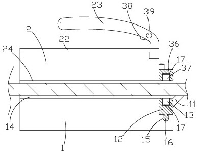
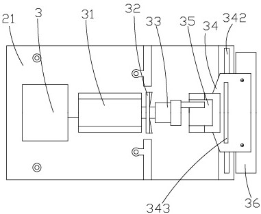
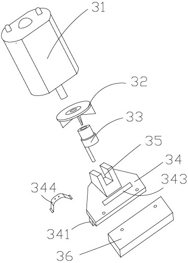

Embodiment Construction

[0023] Embodiments of the present invention will be described in further detail below in conjunction with the accompanying drawings.

[0024] Figure 1 to Figure 4 It is a structural schematic diagram of the present invention.

[0025] The reference signs are: cylinder inner brush 1, long bristles 11, cleaning head 12, inner magnet 13, cleaning unit 14, chute 15, slide rail 16, shielding seat 17, cylinder outer brush 2, installation cavity 21, cover Plate 22, handle 23, fluff surface 24, battery 3, motor 31, fan 32, eccentric head 33, connecting frame 34, limiting convex body 341, limiting groove 342, limiting square groove 343, shrapnel 344, bayonet 35 , drive head 36, outer magnet 37, switch 38, governor 39.

[0026] Figure 1 to Figure 4 It is a structural schematic diagram of the present invention.

[0027] A magnetic brush for automatically cleaning fish tanks, comprising an inner brush 1 placed on the inner wall of the fish tank and an outer brush 2 placed on the out...


PUM


Abstract

The invention discloses a magnetic brush for automatically cleaning fish tanks, which comprises a tank inner brush placed on the inner wall of the fish tank and an outer tank brush placed on the outer wall of the fish tank and magnetically attracted to the inner brush in the tank. Both the outer tank brush and the inner brush are equipped with Permanent magnet, the inner side of the brush outside the cylinder and the inner side of the brush inside the cylinder can be attracted to each other through the permanent magnet, the brush outside the cylinder is formed with an installation cavity, the installation cavity is provided with a cover plate, and a drive unit is provided in the installation cavity, the drive unit includes a battery, The motor electrically connected to the battery, the eccentric head connected to the output shaft of the motor, the front end of the installation cavity is provided with a connecting frame, the eccentric shaft at the front end of the eccentric head is inserted into the bayonet of the connecting frame, the front end of the connecting frame is connected with the driving head, and the driving head is set There is at least one outer magnet, and the cleaning head is movably set on the front end of the brush in the tank. The cleaning head is provided with an inner magnet that attracts the outer magnet. A cleaning unit is provided on the surface of the cleaning head in contact with the fish tank. The design is reasonable and the labor intensity is small. , One-time cleaning effect is good.

Description

technical field [0001] The invention relates to a cleaning device, in particular to a magnetic brush for automatically cleaning fish tanks. Background technique [0002] After the fish tank is used for a period of time, stains and algae, such as moss, will accumulate on the inner wall of the fish tank, so it is necessary to replace the water and clean the inner wall of the fish tank regularly. [0003] The existing magnetic brush is composed of an inner brush and an outer brush. Through the adsorption of magnets, the outer brush of the moving cylinder drives the inner brush to move to clean the inner wall of the fish tank. However, some difficulties may appear on the inner wall of the fish tank during the use of the fish tank. To clean up the stains and algae, it is necessary to move the outer brush and the inner brush back and forth to clean these places. During the operation, the outer brush will move too fast, which will cause the inner brush to separate from the outer br...

Claims


Application Information

Patent Timeline
Patent Type & Authority Patents(China)
IPC IPC(8): A46B13/02A46B5/00A46B15/00A01K63/10
CPCA46B5/0012A46B13/02A46B15/0026A46B2200/30A01K63/10
Inventor 卢园园
Owner 临沂高新城乡发展有限公司
Learn More