Split shaping upper punch for powder metallurgy

A powder metallurgy, split-type technology, applied in the field of mechanical equipment, can solve problems such as prolonging the processing cycle, reducing production efficiency, and increasing processing costs, so as to achieve the effect of reducing mold processing costs, avoiding machining procedures, and saving mold costs

Active Publication Date: 2018-07-27
SUZHOU NETABHAPE COMPOSITE MATERIALS
View PDF4 Cites 0 Cited by
  • Summary
  • Abstract
  • Description
  • Claims
  • Application Information

AI Technical Summary

Problems solved by technology

However, if there are surface requirements (such as rounded corners or chamfers) on the inner orifice of the upper punching surface, the structure of the lower mandrel cannot meet the requirements, and it can only be realized by adding machining processes later, which will not only increase the process flow, but also Prolong the processing cycle, reduce production efficiency, and greatly increase processing costs
[0003] For some inner holes, the dimensional accuracy requirements are not high, and there is no need for shaping guarantee, but the inner hole has a surface shape requirement. In this case, if the mandrel with steps is used to process the surface shape, it will waste mold materials. , increasing the complexity of the mold structure will also increase the processing difficulty of the mold and increase the production cost. At the same time, if there are multiple inner hole mandrels, due to the differences in material, processing and deformation of the inner hole mandrels, it may also cause the surface after processing Type consistency is poor

Method used


Image

  • Split shaping upper punch for powder metallurgy
  • Split shaping upper punch for powder metallurgy
  • Split shaping upper punch for powder metallurgy

Examples


Embodiment Construction

[0036] The present invention will be further described below in conjunction with specific examples, but the examples are only exemplary and do not constitute any limitation to the scope of the present invention. Those skilled in the art should understand that the details and forms of the technical solutions of the present invention can be modified or replaced without departing from the spirit and scope of the present invention, but these modifications and replacements all fall within the protection scope of the present invention.

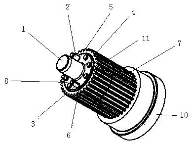
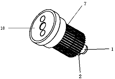
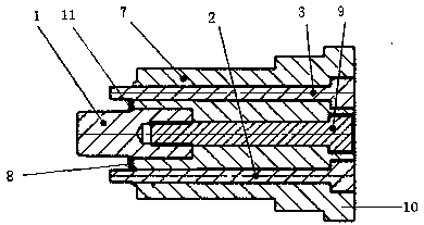
[0037] Such as Figure 1-7 As shown, a powder metallurgy split-type shaping upper punch includes a main mandrel 1, a first side mandrel 2, a second side mandrel 3, an upper outer punch 7 and a screw 9, wherein the upper outer punch 7 includes The end face 8 of the upper punching step, the upper punching base 10 and the fourth surface step 11; the center of the end face 8 of the upper punching step is provided with a socket B, and two sockets A are p...


PUM


Abstract

The invention discloses a split shaping upper punch for powder metallurgy. The split shaping upper punch comprises a main core rod, a first side core rod, a second side core rod, an upper outer punchand a screw, wherein the upper outer punch comprises an upper punch step end surface, an upper punch base and fourth face figure steps; an insert hole B is formed in the center of the upper punch stepend surface, two insert holes A are formed in two sides of a central hole, and the fourth face figure steps are distributed on the same circumference with the insert holes A; a first face figure stepis arranged on the main core rod; the first side core rod and the second side core rod are provided with a second face figure step and a third face figure step respectively. The split shaping upper punch for powder metallurgy is provided, by means of the main core rod and the two embedded side core rods, a port face figure of an inner hole in an upper punch surface of a product is machined whilethe dimensional accuracy of the inner hole is guaranteed; the face figure steps integrated with the upper punch are used for machining a port face figure of an inner hole without shaping need, so thataddition of machining procedures is avoided, process flow and machining period of the product are shortened, and production cost of the product is reduced.

Description

technical field [0001] The invention belongs to the field of mechanical equipment, and in particular relates to a powder metallurgy split type shaping upper punch. Background technique [0002] The shaping of existing powder metallurgy products generally adopts the lower mandrel structure. This structure can ensure good dimensional accuracy of the inner hole. Increase mandrel steps to achieve. However, if there are surface requirements (such as rounded corners or chamfers) on the inner orifice of the upper punching surface, the structure of the lower mandrel cannot meet the requirements, and it can only be realized by adding machining processes later, which will not only increase the process flow, but also Prolonging the processing cycle and reducing production efficiency will greatly increase processing costs. [0003] For some inner holes, the dimensional accuracy requirements are not high, and there is no need for shaping guarantee, but the inner hole has a surface shap...

Claims


Application Information

Patent Timeline
Patent Type & Authority Applications(China)
IPC IPC(8): B22F3/03
Inventor 代超
Owner SUZHOU NETABHAPE COMPOSITE MATERIALS
Why Eureka
Try Eureka