
Timber storing frame with dust removing and collecting functions

A technology for placing racks and wood, applied in the direction of tool storage devices, manufacturing tools, cleaning methods and utensils, etc., can solve problems such as single design, unreasonable design, inability to remove residues and moisture, etc., and achieve the effect of improving the effect

Inactive Publication Date: 2018-07-27
YUNHEMAN WALKER TOYS CO LTD
View PDF0 Cites 1 Cited by
  • Summary
  • Abstract
  • Description
  • Claims
  • Application Information

AI Technical Summary

Problems solved by technology

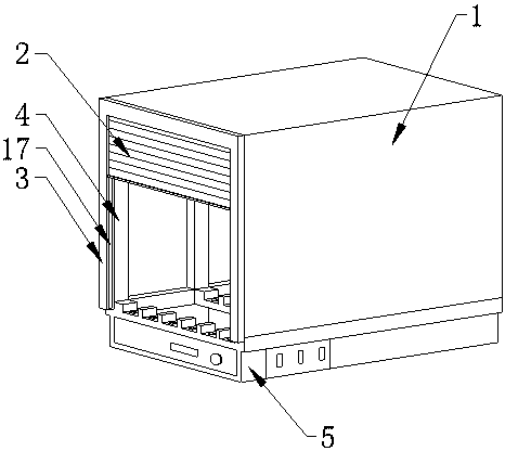
[0004] The purpose of the present invention is to solve the technical problem that the design is single, and the residue and moisture on the surface of the cut wood cannot be removed, and a wood placement rack with dust removal and collection functions is provided. In the device, a dust suction fan is set to The dust suction fan can generate wind, and the air inlet will generate suction. The wind will be inhaled from the curtain, pass through the wood, take away the moisture and wood chips on the surface of the wood, and then enter the air inlet. The wood chips and moisture will be absorbed by the filter layer to achieve The function of removing sawdust and absorbing moisture has wide practicability to solve the unreasonable and single design of the existing wood placement frame proposed in the above-mentioned background technology, and cannot remove the residue and moisture on the surface of the cut wood The problem

Method used


Image

  • Timber storing frame with dust removing and collecting functions
  • Timber storing frame with dust removing and collecting functions
  • Timber storing frame with dust removing and collecting functions

Examples


Embodiment Construction

[0024] The following will clearly and completely describe the technical solutions in the embodiments of the present invention with reference to the accompanying drawings in the embodiments of the present invention. Obviously, the described embodiments are only some, not all, embodiments of the present invention. Based on the embodiments of the present invention, all other embodiments obtained by persons of ordinary skill in the art without making creative efforts belong to the protection scope of the present invention.

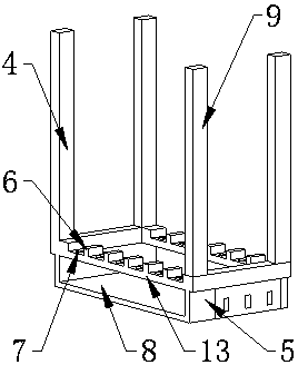
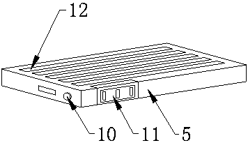
[0025] Device shell 1 used in the present invention, curtain 2, curtain slideway 3, wood placement frame 4, dust suction fan 5, partition 6, pulley 7, vacuum cleaner placement port 8, fixed column 9, power switch 10. The filter chamber 11, the air inlet 12, the bracket 13, the filter layer 14, the door 15, and the air outlet 16 can all be purchased from the market or obtained by private order.

[0026] The model of the dust suction ventilator used in the prese...


PUM


Abstract

The invention provides a timber storing frame with dust removing and collecting functions. The timber storing frame comprises a device outer shell, a timber storing frame body and a dust sucking ventilating machine. The device outer shell is located on the upper portion of the dust sucking ventilating machine and is in a 'cuboid' shape. The device outer shell is embedded into the dust sucking ventilating machine. The timber storing frame body is located on the top surface of the dust sucking ventilating machine. The timber storing frame body and the top surface of the dust sucking ventilatingmachine are welded and fixed. The timber storing frame body is wrapped with the device outer shell. The timber storing frame with the dust removing and collecting functions is provided with the dust sucking ventilating machine, the dust sucking ventilating machine is composed of an air pump, the dust sucking ventilating machine is started, then an air inlet produces sucking force, air is sucked from one side of a pull curtain and passes through the surface of timber to take away residue wood dust and moisture on the surface of the timber, and enters the air inlet, the wood dust enters the dustsucking ventilating machine to enter a filtering bin at the front end, the filtering bin is internally provided with a filtering layer, the filtering layer is composed of a sponge layer, the wood dust and water can be filtered, and the effects of removing residues and the water are achieved.

Description

technical field [0001] The invention relates to the technical field of wood processing, in particular to a wood placing frame. Background technique [0002] The wood placing rack is a placing rack specially used for placing cut wood. [0003] Existing wood storage racks have a single design and can only place cut wood simply. There are sawdust in the freshly cut wood, which will damage the environmental sanitation, and the wood has a certain amount of moisture just after cutting. If it is not air-dried in time, the wood will be damaged. Mold, reducing the quality of wood. Contents of the invention [0004] The purpose of the present invention is to solve the technical problem that the design is single, and the residue and moisture on the surface of the cut wood cannot be removed, and a wood placement rack with dust removal and collection functions is provided. In the device, a dust suction fan is set to The dust suction fan can generate wind, and the air inlet will gener...

Claims


Application Information

Patent Timeline
IPC IPC(8): B25H3/04B08B5/04
CPCB25H3/04B08B5/04
Inventor 王婷
Owner YUNHEMAN WALKER TOYS CO LTD
Learn More