Batch ceramic tile cutting device

A cutting device and batch technology, applied in the direction of work accessories, manufacturing tools, stone processing equipment, etc., can solve the problems of low work efficiency, manual placement and removal of tiles, etc., and achieve the effect of improving cutting efficiency and reducing energy consumption

Inactive Publication Date: 2018-07-27
重庆谦谦装饰工程有限公司
View PDF5 Cites 5 Cited by
  • Summary
  • Abstract
  • Description
  • Claims
  • Application Information

AI Technical Summary

Problems solved by technology

[0004] The purpose of the present invention is to provide a tile batch cutting device to solve the problem of low work efficiency due to manual placement and removal of tiles during the tile cutting process in the prior art

Method used


Image

  • Batch ceramic tile cutting device
  • Batch ceramic tile cutting device
  • Batch ceramic tile cutting device

Examples


Embodiment 1

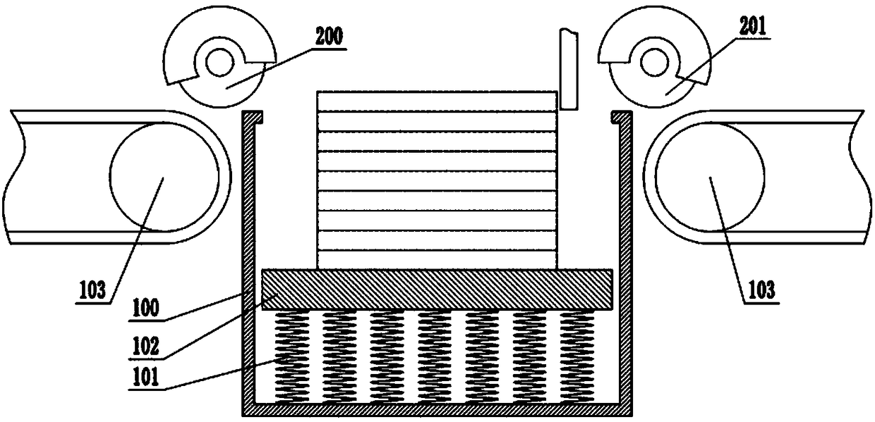
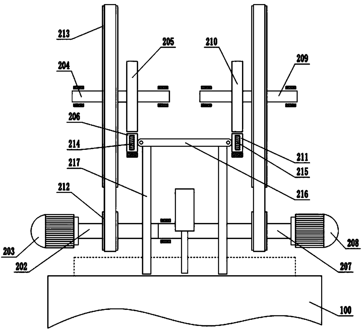
[0026] Such as figure 1 Shown is the first embodiment of the present invention, which announces a ceramic tile batch cutting device, including a frame, a working box 100 and a cutting device, an elastic member 101 is arranged at the bottom of the working box 100, and a support plate 102 is arranged above the elastic member 101 , when no tiles are placed on the support plate 102, the support plate 102 is higher than the upper surface of the work box 100, and the height of the support plate 102 beyond the surface of the work box 100 is the thickness of a tile, wherein the elastic member 101 can adopt devices such as springs, And every time a ceramic tile is placed on the support plate 102, the elastic member 101 moves downward by a displacement of the thickness of the ceramic tile, so that during the continuous processing of multiple ceramic tiles, one ceramic tile is exposed from the upper surface of the work box 100 for cutting. ; The left and right sides of the working box 10...

Embodiment 2

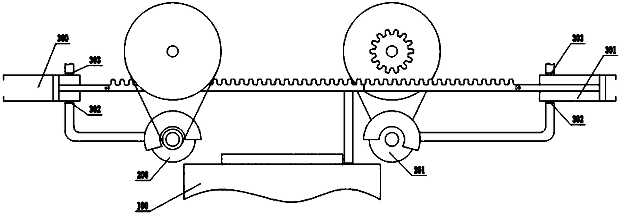
[0032] Such as image 3 Shown is Embodiment 2 of the present invention, and the difference from Embodiment 1 is: the first air cylinder 300 fixed on the frame is hinged at the left end of the first rack 206, and the right end of the second rack 211 is hinged with a cylinder fixed on the frame. On the second cylinder 301 on the first cylinder 300 and the cylinder side wall on the side of the piston rod of the second cylinder 301 are provided with an intake check valve 302 and an air outlet check valve 303, the first cutting wheel 200 and the second The periphery of cutting wheel 201 is provided with a semicircular casing, and the casing is provided with an air inlet, and the intake check valve 302 of the first cylinder 300 and the second cylinder 301 is connected to the first cutting wheel 200 and the second through the pipeline respectively. The suction port on the casing of the cutting wheel 201 is connected, and each air outlet check valve 303 is connected with a recovery de...


PUM


Abstract

The invention belongs to the technical field of cutting equipment and particularly discloses a batch ceramic tile cutting device. The device comprises a working box and a cutting mechanism, wherein anelastic part is arranged at the bottom of the working box, a support plate is connected with the upper end of the elastic part, and a transfer device is also arranged; the cutting mechanism comprisesa first cutting wheel and a second cutting wheel, the first cutting wheel is fixed on a first rotating shaft driven by a forward rotation motor, a first support shaft is arranged above the first rotating shaft, a first gear is fixed on the first support shaft, and a first rack is arranged below the first gear; the second cutting wheel is fixed on a second rotating shaft driven by a reverse rotation motor, a second support shaft is arranged above the second rotating shaft, a second gear is fixed on the second support shaft, and a second rack is arranged below the second gear; a first electromagnet is arranged in the first rack, a second electromagnet is arranged in the second rack, a support rod is hinged between the first rack and the second rack, and a push rod is connected to the support rod. The device requires no manual taking and placement in the ceramic tile cutting process and has high working efficiency.

Description

technical field [0001] The invention relates to the technical field of cutting equipment, in particular to a tile batch cutting device. Background technique [0002] People often use hand-held cutters when cutting tiles, which not only has low work efficiency, but also produces a lot of dust during the cutting process. Long-term exposure of workers will have a great impact on health. In order to solve this problem, the patent The Chinese invention patent with publication number: CN106142366A discloses a quick cutting device for mosaic tiles. In this patent, the tiles are placed on the cutting table before cutting, and an adjusting device is used to connect the driving device of the cutting wheel and the cutting table. , so that the cutting table moves towards the direction of the cutting wheel, and after the tiles are cut, the tiles are removed; in addition, a dust suction device is installed above the cutting table. Although this patent solves the problem of cutting with a...

Claims


Application Information

Patent Timeline
Patent Type & Authority Applications(China)
IPC IPC(8): B28D1/24B28D7/00B28D7/04
CPCB28D1/24B28D7/00B28D7/04
Inventor 张谦
Owner 重庆谦谦装饰工程有限公司
Why Eureka
Try Eureka