Novel siphon type drainage device for cooling cylinder

A drainage device and straw-type technology, applied in textiles and papermaking, papermaking, papermaking, etc., can solve problems such as troublesome installation and maintenance work, and achieve the effects of easy maintenance, less water accumulation in the tank, and simple structure

Inactive Publication Date: 2018-07-27
马海燕
View PDF0 Cites 0 Cited by
  • Summary
  • Abstract
  • Description
  • Claims
  • Application Information

AI Technical Summary

Problems solved by technology

The device is equipped with two rotary joints. When installing and overhauling the cooling water pipe, people need to enter the inside of the drying cylinder. The installation and overhaul work is cumbersome.

Method used


Image

  • Novel siphon type drainage device for cooling cylinder
  • Novel siphon type drainage device for cooling cylinder
  • Novel siphon type drainage device for cooling cylinder

Examples


Embodiment Construction

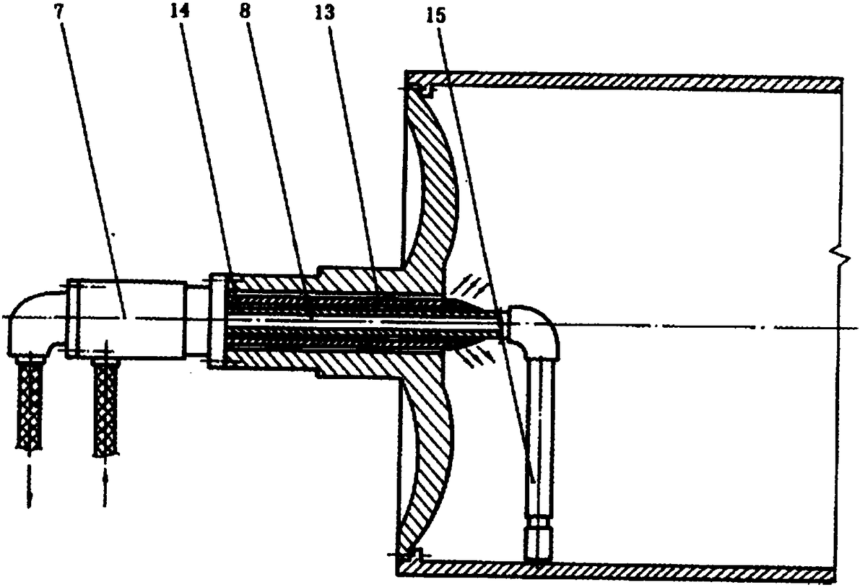
[0015] exist image 3 and Figure 4 In the specific embodiment shown, the drainage horizontal pipe (14) of the novel straw-type cold cylinder drainage device forms a coaxial casing structure inside the water inlet pipe (13) and the water inlet pipe (13), and one end of the water inlet pipe (13) is fixed Inside the rotary joint housing (10) and sealed by an O-ring (16), the other end is closed in the outer diameter of the drain horizontal pipe (14) inside the cold cylinder, and a water spray hole is drilled at the end to the inside of the cold cylinder Spray water, one end of the drainpipe horizontal pipe (14) is fixed inside the swivel joint swivel joint housing (10) and sealed by an O-ring (17), and the other end is connected to the drain vertical pipe (15) inside the cold cylinder. The support sleeve (9) of the rotary joint is fixed on the shaft head of the drying cylinder by a flange, and the external support sleeve supports the rotary joint shell (10) through two sets of ...


PUM


Abstract

The invention relates to a cooling water drainage device for cooling cylinders in the industry of papermaking and the like, in particular to a novel siphon type drainage device for a cooling cylinder.The device mainly comprises a self-supporting rotating joint and a siphon, a horizontal drainage pipe and a water inlet pipe forming the siphon are of a concentric sleeving structure, one end of thewater inlet pipe is fixed in a casing of the rotating joint, the other end is closed on the outer diameter of the horizontal drainage pipe, and a water spraying hole is drilled in the end part to spray water into the cooling cylinder. One end of the horizontal drainage pipe is fixed in the casing of the rotating joint, and the other end is connected with a vertical drainage pipe in the cooling cylinder. The rotating joint is supported on a shaft head of the cooling cylinder through a support sleeve and a bearing, and after compressed air under 0.01-0.05 MPa is introduced into the cylinder viaan air hole in the rotating joint, cooling water in the cooling cylinder can be continuously drained.

Description

technical field [0001] The invention relates to a cooling water discharge device for cold cylinders in industries such as papermaking, in particular to a novel suction pipe type cold cylinder drainage device. Background technique [0002] There are three main types of cold cylinder drainage devices commonly used at present. [0003] One is a bucket type drainage device, and the bucket is fixed on the cylinder head of the transmission side in the drying cylinder. When the drying cylinder is rotated, the bucket will pour cooling water into the lower part of the drying cylinder, and then flow into the annular space between the inner wall of the shaft head and the air supply pipe to discharge. The drainage device of the cold cylinder with this structure is more complicated, and the drainage is intermittent and uneven. But when the vehicle speed is higher than 350-400 m / min, the cooling water is subjected to centrifugal force and forms a condensed water ring, and the required dr...

Claims


Application Information

Patent Timeline
Patent Type & Authority Applications(China)
IPC IPC(8): D21F7/00
CPCD21F7/00
Inventor 不公告发明人
Owner 马海燕
Why Eureka
Try Eureka