Continuously drained steam trap valve

A steam trap and steam technology, applied in the direction of steam traps, mechanical equipment, etc., can solve the problems of short service life, waste of energy, waste of steam, etc., and achieve the effects of avoiding steam leakage, long service life and wide adjustment range

Inactive Publication Date: 2015-12-30
NANJING RECLAIMER ENVIRONMENTAL TEKNIK
View PDF8 Cites 0 Cited by
  • Summary
  • Abstract
  • Description
  • Claims
  • Application Information

AI Technical Summary

Problems solved by technology

[0003] Currently commonly used steam traps have many deficiencies in terms of structure, technical performance, product quality, and use functions. The main manifestations are: (1) Most of them use mechanical drainage. When working under high load and harsh environments for a long time, the devices are easily damaged. Greatly affect the service life; (2) With intermittent drainage, the valve core is impacted many times, which is easy to cause wear and tear, and is easy to be accompanied by steam leakage, which not only affects production efficiency, but also wastes energy; (3) A little improper operation will cause As a result, the steam trap cannot be closed, resulting in a great waste of steam; (4) The failure rate is high, which increases the maintenance cost and the service life is short; (5) The condensate discharge cannot be automatically adjusted, and the process system cannot be guaranteed to be in the best working condition
[0004] Chinese patent 201320598170.5 provides an energy-saving steam trap that can adjust the discharge of condensed water, but its disadvantage is that the structure is relatively complicated

Method used


Image

  • Continuously drained steam trap valve

Examples


Embodiment 1

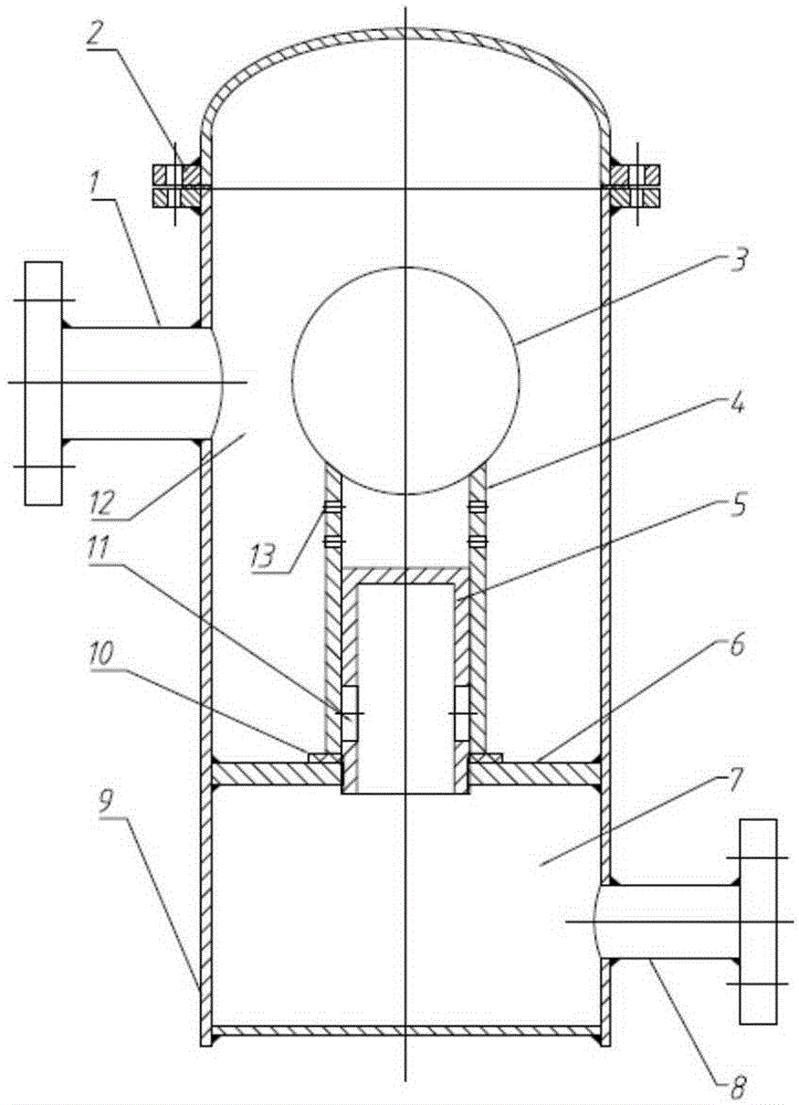
[0032] Such as figure 1 Shown is a structural schematic diagram of a continuous drainage steam trap of the present invention.

[0033] Below by specific embodiment, in conjunction with its accompanying drawing, this scheme is elaborated:

[0034] A steam trap for continuous drainage, the steam trap includes a valve body 9 and a valve core 4, the upper end of the valve core 4 is connected with a hydrophobic function module 3, the valve body 9 is provided with a steam-water mixture inlet 1 and a condensation Water outlet 8, the valve body 9 is fixedly connected with a valve seat 6, the valve seat 6 divides the inner cavity of the valve body 9 into an upper cavity 12 and a lower cavity 7, and a guide rail 5 is fixed on the valve seat 6, The valve core 4 is installed in the cavity of the valve body 9 through the guide rail 5. The guide rail 5 adopts a hollow structure. In communication, the condensed water outlet 8 communicates with the lower cavity 7; the upper end surface of t...


PUM


Abstract

The invention relates to a continuously drained steam trap valve. The steam trap valve comprises a valve body and a valve element, wherein the valve element is arranged in the cavity of the valve body through a guide rail, when the valve element floats, condensed water is drained out through a condensed water outlet by passing through a drain hole of the guide rail, the dewatering amount is automatically adjusted, continuous dewatering can be realized, the leakage rate of steam is low, and finally the aim of improving the system heat efficiency is achieved.

Description

technical field [0001] The invention relates to a continuous drainage steam trap, which belongs to the technical field of valves. Background technique [0002] Steam is a secondary energy source in many industrial fields, and steam traps are important control valves to ensure the normal operation of steam systems and save energy. The function of the steam trap is to discharge the condensed water, gas and other non-condensable gases in the steam system as soon as possible, and at the same time prevent the leakage of steam to the greatest extent. [0003] Currently commonly used steam traps have many deficiencies in terms of structure, technical performance, product quality, and use functions. The main manifestations are: (1) Most of them use mechanical drainage. When working under high load and harsh environments for a long time, the devices are easily damaged. Greatly affect the service life; (2) With intermittent drainage, the valve core is impacted many times, which is ea...

Claims


Application Information

Patent Timeline
Patent Type & Authority Applications(China)
IPC IPC(8): F16T1/38F16T1/00
Inventor 王海波彭启勇吴明
Owner NANJING RECLAIMER ENVIRONMENTAL TEKNIK
Why Eureka
Try Eureka