Negative-pressure drainage device

A negative pressure drainage and drainage tube technology, applied in the field of medical devices, can solve the problems of continuous drainage, inconvenient cleaning, low work efficiency, etc., and achieve the effects of high drainage work efficiency, convenient cleaning and convenient application.

Inactive Publication Date: 2013-04-24
THE THIRD AFFILIATED HOSPITAL OF THIRD MILITARY MEDICAL UNIV OF PLA
View PDF6 Cites 0 Cited by
  • Summary
  • Abstract
  • Description
  • Claims
  • Application Information

AI Technical Summary

Problems solved by technology

The artificial negative pressure drainage device will have a small amount of drainage backflow and insufficient pressure in the process of creating negative pressure, and the drainage is inconvenient to pour out or clean, etc.
The central negative pressure drainage bottle has the disadvantages that once the central negative pressure stops, there will be no negative pressure, it cannot be used, and it is inconvenient to pour out and clean.
In the prior art, the artificial negative pressure drainage device can only generate negative pressure manually, but cannot rely on external power such as negative pressure suction device to generate negative pressure. Manual operation is more laborious to generate negative pressure; the central negative pressure drainage bottle can only rely on negative pressure. Negative pressure is generated by external power such as the suction device, but negative pressure cannot be generated manually. When the vacuum pump fails, the negative pressure suction device will not work.
Moreover, in the negative pressure drainage device in the prior art, after the drainage fluid enters the negative pressure chamber, the negative pressure drainage cannot be performed. After one drainage, the drainage device needs to be removed to discharge the drainage fluid and then the drainage can be performed. The drainage work can only be carried out intermittently. Continuous drainage is not possible, and work efficiency is low
[0003] Therefore negative pressure device in the prior art all has defect in use

Method used


Image

  • Negative-pressure drainage device
  • Negative-pressure drainage device
  • Negative-pressure drainage device

Examples


Embodiment Construction

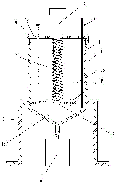
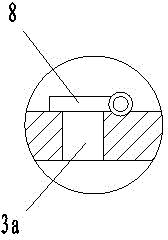
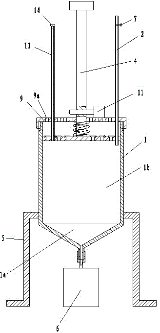
[0018] figure 1 It is a structural schematic diagram of the negative pressure diverter of the present invention; figure 2 for figure 1 Enlarged view of part P in the center; image 3 It is a schematic diagram of the first negative pressure drainage state of the negative pressure drainage device of the present invention; Figure 4 It is a schematic diagram of the second negative pressure drainage state of the negative pressure drainage device of the present invention.

[0019] As shown in the figure, the negative pressure drainage device of this embodiment includes a cylinder 1, a drainage tube 2, a piston plate 3 that is sealingly matched with the inner wall of the cylinder, a piston rod 4 arranged on the piston plate, and a bracket for supporting the cylinder 5. The piston plate divides the inner cavity of the cylinder into a lower cavity 1a and an upper cavity 1b. The lower cavity is a negative pressure generating cavity, and the upper cavity communicates with the atmosp...


PUM


Abstract

The invention discloses a negative-pressure drainage device, which comprises a cylinder, a drainage tube, a piston plate, a piston rod and a bracket. The cavity of the cylinder is divided by the piston plate into an upper cavity and a lower cavity, the upper cavity is communicated with the atmosphere, and the bottom of the lower cavity is connected with a removable liquid storage device; the liquid discharging port of the drainage tube is communicated with the lower cavity, and the drainage tube is provided with a valve; and the piston plate is provided with an air vent communicated with the upper cavity and the lower cavity, and the upper surface of the piston plate is hinged with a cover plate used for sealing the air vent. When the piston plate moves downwards, air in the lower cavity can be ejected to open the cover plate to flow into the atmosphere through the air vent, negative pressure can be formed in the lower cavity after the piston plate moves upwards, continuous drainage can be achieved by the negative-pressure drainage device, and the working efficiency is high; the valve on the drainage tube can be closed to avoid liquid backflow during drainage; the liquid storage device can be removed to completely discharge liquid in the lower cavity, and cleaning can be facilitated; and the negative pressure can be produced manually or with the negative-pressure drainage device, and the negative-pressure drainage device has high practicality and can be used conveniently.

Description

technical field [0001] The invention relates to a medical device, in particular to a device utilizing negative pressure drainage. Background technique [0002] Negative pressure drainage is widely used in clinical practice. For patients after surgery, the purpose of negative pressure drainage is twofold. One is to draw out the liquid exuded from the wound surface; the other is to shrink the wound cavity through negative pressure. , conducive to wound tissue healing. This requires that the negative pressure must have a certain pressure and be continuous, so that the wound cavity can be reduced. In addition, the drainage must have a pipeline, and the negative pressure must be maintained. There are many negative pressure drainage devices clinically used, but basically the negative pressure and drainage are in the same container, such as artificial negative pressure drainage balls, artificial negative pressure drainage bottles, central negative pressure drainage bottles, etc. ...

Claims


Application Information

Patent Timeline
Patent Type & Authority Patents(China)
IPC IPC(8): A61M27/00
Inventor 文亚渊黄泽民叶自林陈宇
Owner THE THIRD AFFILIATED HOSPITAL OF THIRD MILITARY MEDICAL UNIV OF PLA
Why Eureka
Try Eureka