An annular float spool type steam trap
A ring-shaped float and steam trap technology, applied in steam traps, valve details, valve devices, etc., to achieve reliable performance, low cost of manufacturing, assembly, use and maintenance, and long service life
- Summary
- Abstract
- Description
- Claims
- Application Information
AI Technical Summary
Problems solved by technology
Method used
Image
Examples
Embodiment Construction
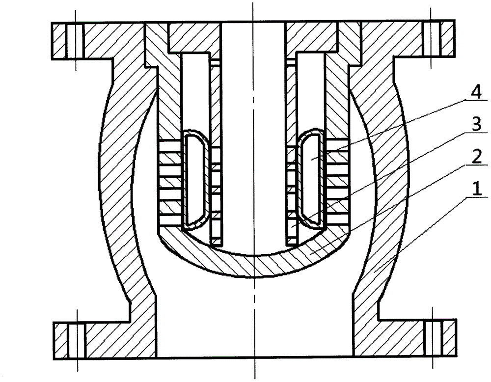
[0015] An annular float spool type steam trap is composed of a valve body 1, a valve seat 2, a downcomer 3, and an annular float spool 4; The upper end is connected with the upper end of the valve seat 2, and the annular float spool 4 is installed between the valve seat 2 and the downcomer 3.
[0016] The above-mentioned annular float spool type steam trap is characterized in that: the valve seat 2 is a blind pipe structure, and the lower half of the pipe wall is circumferentially provided with drainage screen holes.
[0017] The above-mentioned annular float spool type steam trap is characterized in that: the lower half of the downcomer 3 is provided with drainage screen holes in the circumferential direction, and a pair of balance holes are provided in the upper circumferential direction.
[0018] The above-mentioned annular float spool type steam trap is characterized in that: the annular float spool 4 is a hollow annular body.
PUM
 Abstract
Description
Claims
Application Information
 - R&D
- Intellectual Property
- Life Sciences
- Materials
- Tech Scout
- Unparalleled Data Quality
- Higher Quality Content
- 60% Fewer Hallucinations
Browse by: Latest US Patents, China's latest patents, Technical Efficacy Thesaurus, Application Domain, Technology Topic, Popular Technical Reports.
© 2025 PatSnap. All rights reserved.Legal|Privacy policy|Modern Slavery Act Transparency Statement|Sitemap|About US| Contact US: help@patsnap.com

