Structured light projection apparatus, depth camera, and depth image imaging method based on depth camera

A technology of a projection device and a depth camera, which is applied in the field of optical imaging, can solve problems such as unclear outgoing structured light patterns, undisclosed outgoing structured light patterns, etc., and achieve the effect of increasing the use scene

Pending Publication Date: 2018-07-27
NINGBO SUNNY OPOTECH CO LTD
View PDF12 Cites 19 Cited by
  • Summary
  • Abstract
  • Description
  • Claims
  • Application Information

AI Technical Summary

Problems solved by technology

The device only discloses that it can emit structured light patterns that change in at least one dimension, but does not disclose how to emit the changed structured light patterns, making it unclear to those skilled in the art how to emit different structured light patterns

Method used


Image

  • Structured light projection apparatus, depth camera, and depth image imaging method based on depth camera
  • Structured light projection apparatus, depth camera, and depth image imaging method based on depth camera
  • Structured light projection apparatus, depth camera, and depth image imaging method based on depth camera

Examples


Embodiment 1

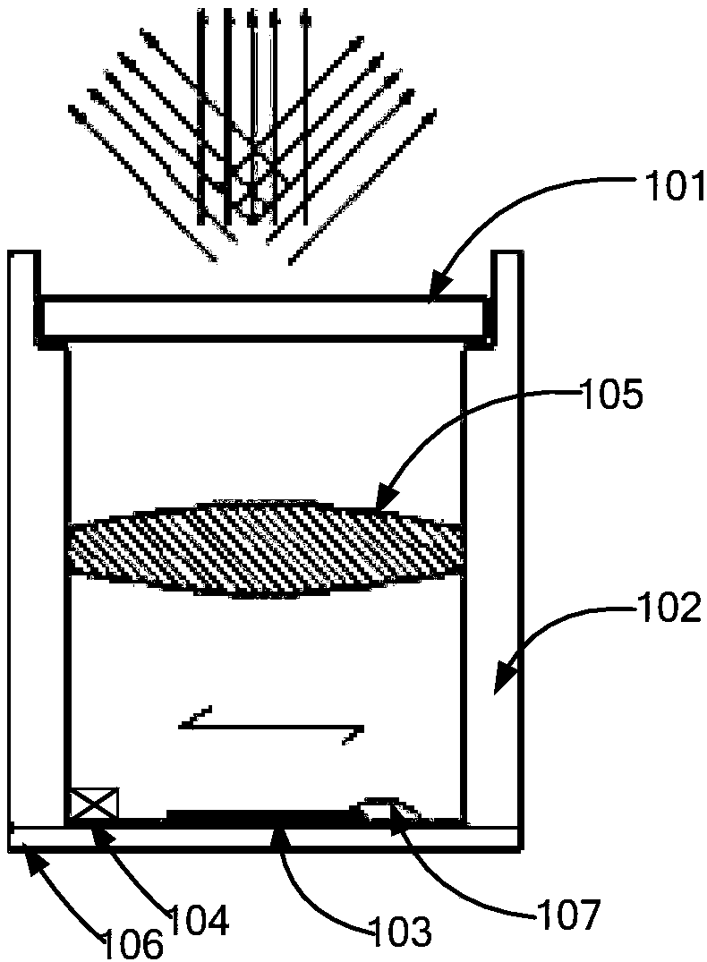
[0085] figure 1 is a schematic structural view of the structured light projection device provided in Example 1. Such as figure 1 As shown, the structured light projection device provided in this embodiment includes a diffractive optical element (DOE) 101 , a support 102 , a light source 103 , a first driver 104 , a collimating lens system 105 , a circuit board 106 , and a gold wire 107 .

[0086] The support member 102 is installed on the circuit board 106, for example, the support member 102 is bonded to the circuit board 106 by using a dispensing process. It can be understood that the installation process can be other processes besides dispensing. In order to avoid the gold wire 107 , there is a certain distance between the supporting member 102 and the light source 103 . The light source 103 is directly mounted on the circuit board 106 . A limit table is provided on the support member 102 for fixing and supporting the DOE 101 and the collimating lens system 105 . The fi...

Embodiment 2

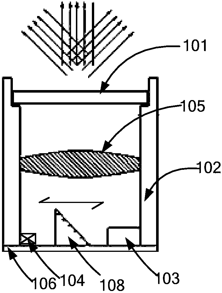
[0091] figure 2 is a schematic structural view of the structured light projection device provided in Embodiment 2. Such as figure 2 As shown, the structured light projection device provided in this embodiment adds a reflective element 108 to the device provided in Embodiment 1. The light source 103 is fixedly installed on the circuit board 106 close to the supporting member 102 , and emits a light beam parallel to the circuit board 106 . The reflective element 108 is driven and installed on the circuit board 106 , and can reflect the light beam emitted by the light source 103 to the collimating lens system 105 .

[0092] In this embodiment, the first driving member 104 drives the reflective element 108 to move horizontally on the circuit board 106 to change the position where the reflected light beam irradiates the DOE 101 to change the working area of ​​the DOE 101 . Since the patterns of the DOE 101 used in this embodiment are inconsistent, when the beam irradiation pos...

Embodiment 3

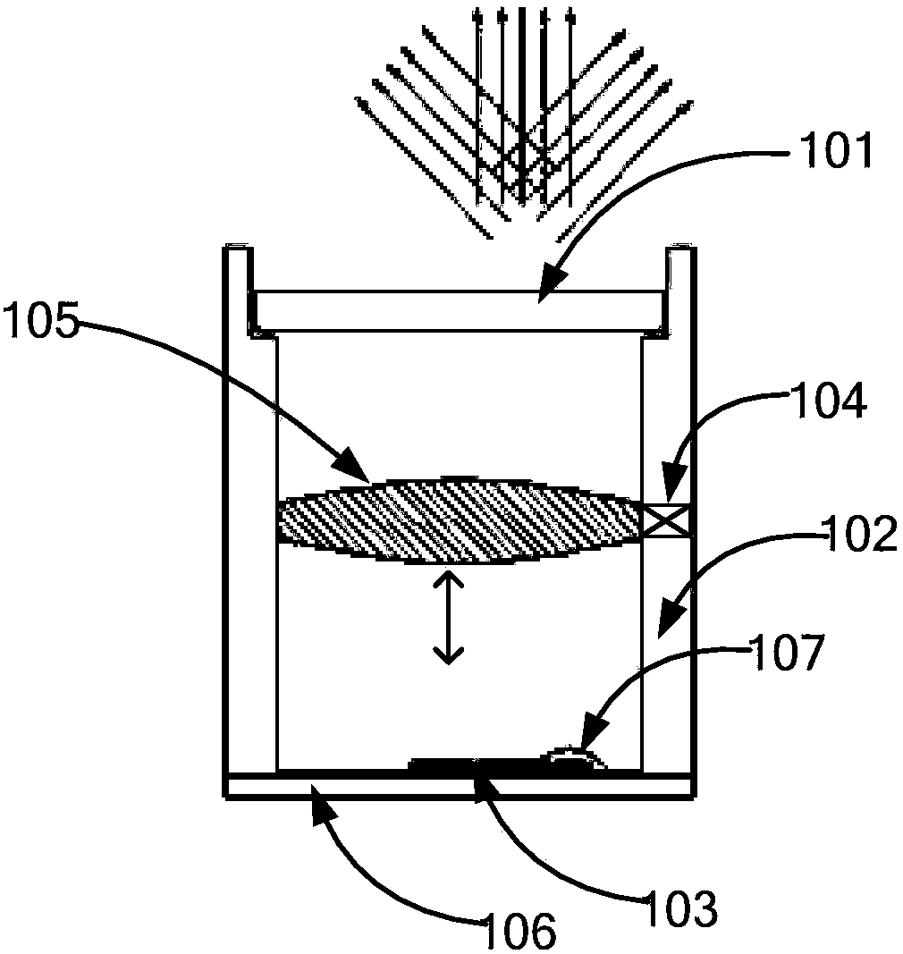
[0095] image 3 is a schematic structural view of the structured light projection device provided in Example 3. Such as image 3 As shown, the structured light projection device provided in this embodiment is basically the same as the device provided in Embodiment 1, except that the first driving member 104 is disposed on the support member 102 and is close to the position of the collimating lens system 105 . The first driving member 104 drives the collimating lens system 105 to move vertically, changing the position area where the light beam is irradiated to the DOE 101 , so as to change the working area of ​​the DOE 101 .

[0096] Driven by the first driving member 104, the collimating lens system 105 can move vertically on the supporting member 102, changing the distance from the collimating lens system 105 to the light source 103, thereby changing the degree of dispersion of the outgoing beam of the collimating lens system 105, As a result, the position area irradiated t...


PUM


Abstract

The invention discloses a structured light projection apparatus. The structured light projection apparatus comprises a light source assembly, a diffractive optical element and a collimating lens system; a light beam from a light source is collimated by the collimating lens system to illuminate the diffractive optical element; the projection apparatus also comprises a first driving part, wherein the first driving part drives the light source assembly or/and the diffractive optical element to enable the light beam and the diffractive optical element to perform relative motion to form a variableworking region on the diffractive optical element; and the variable working region performs diffraction on the light beam to project a variable structured optical pattern. Meanwhile, the invention discloses a depth motor adopting the structured light projection apparatus; and by virtue of the depth camera, the imaging quality of a depth image can be improved, and usage scenarios can be increased.In addition, the invention discloses a depth image imaging method based on the depth camera, wherein the method is high in imaging quality.

Description

technical field [0001] The invention belongs to the field of optical imaging, and in particular relates to a structured light projection device, a depth camera and a depth image imaging method based on the depth camera. Background technique [0002] With the development of science and technology, the depth camera technology is becoming more and more perfect. Because the depth camera has a stronger 3D stereoscopic effect, and has the advantages of stronger authenticity, high precision, and high safety factor, the depth camera is gradually being applied to various mobile terminals. [0003] The structured light projection device is an important component of the depth camera, and its function directly affects the function of the entire depth camera. For example, the poor projection effect of the structured light projection module will make the imaging quality of the entire depth camera poor. [0004] The principle of the structured light projection device is that the light beam...

Claims


Application Information

Patent Timeline
Patent Type & Authority Applications(China)
IPC IPC(8): G03B21/20G03B17/54H04N13/204
CPCG03B17/54G03B21/2033G03B21/206
Inventor 陈振宇陈飞帆姚立锋戎琦潘民杰
Owner NINGBO SUNNY OPOTECH CO LTD
Why Eureka
Try Eureka