Pure electric vehicle drive motor

A pure electric vehicle, driving motor technology, applied in the direction of electric vehicles, motors, electric components, etc., can solve the problems of motor damage, can not meet the needs of customers, does not have buffer protection, etc., to achieve convenient operation, simple structure, easy to install and the effect of disassembly and repair

Active Publication Date: 2018-07-27
ZHEJIANG JEAMO MOTOR
View PDF5 Cites 13 Cited by
  • Summary
  • Abstract
  • Description
  • Claims
  • Application Information

AI Technical Summary

Problems solved by technology

Compared with the prior art, the present invention has the advantages of making the wind generated during the running of the car flow smoothly through the surface of the casing and improving the heat dissipation effect of the motor, but the motor is not easy to disassemble and maintain, and does not have the function of buffer protection , the motor will be slightly damaged when the car is running on a bumpy road, which cannot meet the needs of customers

Method used


Image

  • Pure electric vehicle drive motor
  • Pure electric vehicle drive motor
  • Pure electric vehicle drive motor

Examples


Embodiment 1

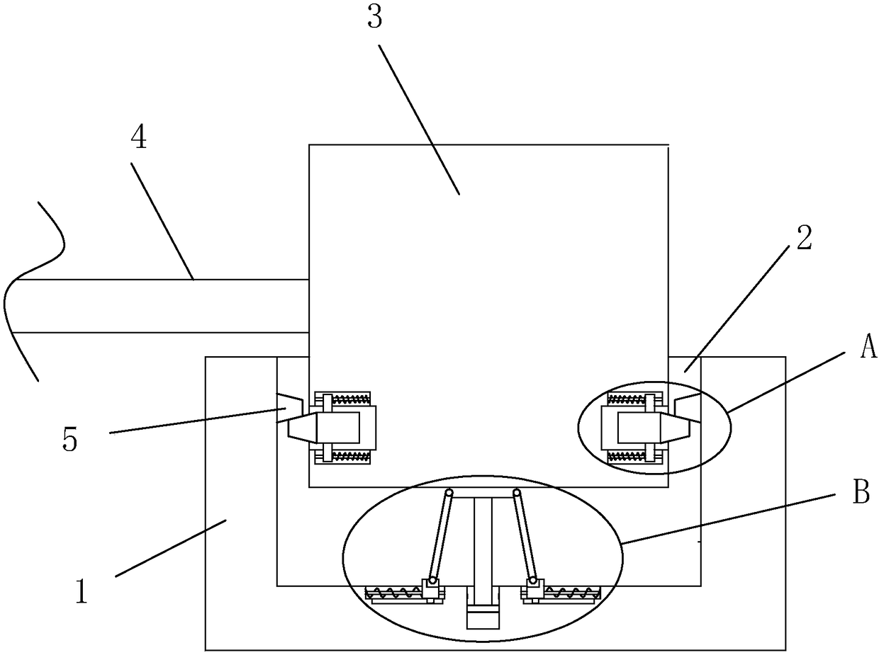
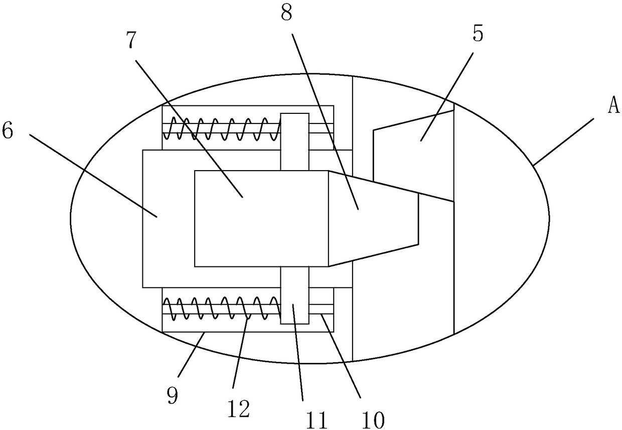
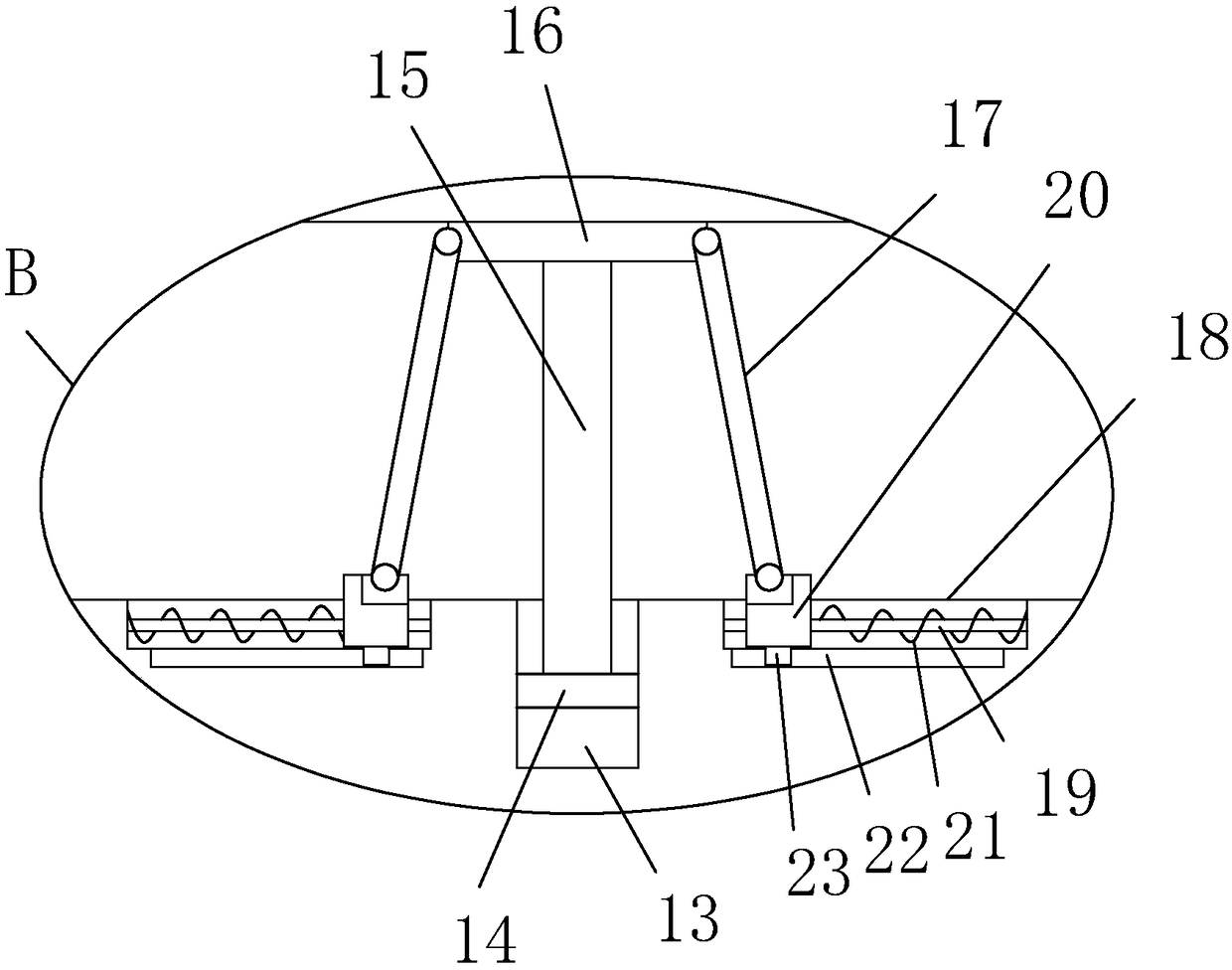
[0046] refer to Figure 1-5 , a pure electric vehicle drive motor is proposed in this embodiment, including a mounting base 1, a mounting groove 2 is provided on the top side of the mounting base 1, a motor body 3 is installed in the mounting groove 2, and a motor body 3 is provided on one side The output shaft 4, the first trapezoidal block 5 is fixedly installed on the inner wall of both sides of the installation groove 2, the both sides of the motor body 3 are provided with a groove 6, and a slider 7 is slidably installed in the groove 6, and the two sliders 7 are fixedly installed with a second trapezoidal block 8 on one side away from each other, the first trapezoidal block 5 is compatible with the second trapezoidal block 8, and the side of the second trapezoidal block 8 away from the slider 7 extends to the outside of the groove 6 and In contact with the first trapezoidal block 5, a first limiting groove 9 is provided on the inner wall of the top side and the inner wall...

Embodiment 2

[0051] refer to Figure 6-13 , this embodiment also includes the following features on the basis of Embodiment 1: the motor body is connected with a cooling assembly; the cooling assembly includes a radiator 90, and is used to transport cooling fluid to circulate between the motor body and the radiator Fluid pump 80 for flow.

[0052] The liquid pump includes a pump casing, a cover body sealingly connected to the open end of the pump casing, a water wheel installed in the pump casing to rotate, and a servo motor connected to the outside of the pump casing to drive the water wheel to rotate through magnetic transmission.

[0053] An overall U-shaped fixing belt 84 for fixing the servo motor is connected to the base by screws.

[0054] The outer wall of the pump housing is integrally formed with a seat body 810, the servo motor is fixedly mounted on the seat body; a drive turntable 86 is fixedly connected to the output shaft of the servo motor, and a drive turntable is fixedly ...


PUM


Abstract

The invention discloses a pure electric vehicle drive motor. The motor comprises a mounting seat, a mounting slot is formed in a top side of the mounting seat, a motor body is mounted in the mountingslot, an output shaft is arranged on one side of the motor body, first trapezoidal blocks are fixedly mounted on inner walls of two sides of the mounting slots, grooves are formed in both sides of themotor body, sliding blocks are slidably mounted in the grooves, second trapezoidal blocks are fixedly mounted on sides, away from each other, of the sliding blocks, the first trapezoidal blocks are adapted to the second trapezoidal blocks, one ends, away from the sliding blocks, of the second trapezoidal blocks extend out of the grooves and are in contact with the first trapezoidal blocks, firstlimiting slots are formed in the top side inner walls and the bottom side inner walls of the grooves, and first limiting blocks are fixedly mounted on the top side and the bottom side of the sliding blocks. According to the motor, the motor body is convenient to install, disassemble and maintain, the function of buffer protection for the motor body is achieved, and the motor has the advantages ofsimple structure and convenient operation.

Description

technical field [0001] The invention relates to the technical field of drive motors, in particular to a drive motor for pure electric vehicles. Background technique [0002] Motor refers to an electromagnetic device that realizes the conversion or transmission of electric energy according to the law of electromagnetic induction. Its main function is to generate driving torque, which is used as a power source for electrical appliances or various machines, and converts mechanical energy into electric energy. [0003] Patent No. 201320244289.2, a pure electric vehicle drive motor invention patent, discloses a drive motor, including a casing, a stator and a rotor arranged in the casing, a rear end cover and a front end cover arranged at the front and rear ends of the casing , the end cover connecting bolts that fix the rear end cover and the front end cover on the casing, and the bearings arranged in the rear end cover and the front end cover, which are characterized in that the...

Claims


Application Information

Patent Timeline
Patent Type & Authority Applications(China)
IPC IPC(8): H02K5/24H02K9/19H02K7/14H02K5/20H02K51/00H02K5/18
CPCH02K5/18H02K5/20H02K5/24H02K7/14H02K9/19H02K51/00Y02T10/64
Inventor 吴彦均
Owner ZHEJIANG JEAMO MOTOR
Why Eureka
Try Eureka