Lighting fixture and lighting fixture control method
A technology for lighting lamps and lamp switches, which is applied in energy-saving control technology, the use of semiconductor lamps, electrical components, etc., can solve problems such as loop errors and lamps cannot be turned on, to prevent loop errors, suitable for promotion and use, and ensure working conditions stable effect
- Summary
- Abstract
- Description
- Claims
- Application Information
AI Technical Summary
Problems solved by technology
Method used
Image
Examples
Embodiment approach 1
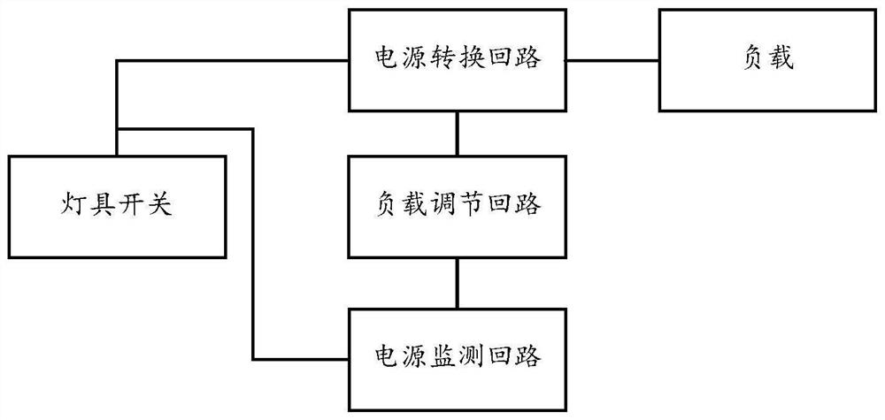
[0041] The first embodiment of the present invention provides a lighting fixture, which is powered by the mains, see figure 1 shown, including:
[0042] Lamp switch, used to control the mains input of lighting fixtures;
[0043] The power conversion circuit is electrically connected with the lamp switch, and is used to convert the input power of the mains into the output power for supplying power to the load;
[0044] The power monitoring circuit is electrically connected to the lamp switch, and is used to monitor whether the lamp is powered on;
[0045] The load regulation circuit is electrically connected with the power monitoring circuit and the power conversion circuit, and communicated with the external operation port, and is used to control the output characteristics of the power conversion circuit according to the load regulation signal sent by the external operation port;
[0046] When the power supply monitoring circuit detects that the lamp switch lights up the lig...
Embodiment approach 2
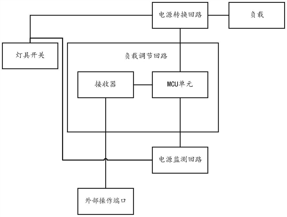
[0053] The second embodiment of the present invention provides a lighting fixture, and the second embodiment is a further improvement of the first embodiment; the main improvement is that in the second embodiment of the present invention, see figure 2 As shown, the load regulation loop consists of:
[0054] The receiver is used to receive the load regulation signal sent by the external operation port;
[0055] The MCU unit is electrically connected with the power monitoring circuit, the receiver and the power conversion circuit, and is used to send a PWM signal to the power conversion circuit according to the load adjustment signal received by the receiver;
[0056] The MCU unit does not respond to the received load adjustment signal within a preset time after receiving the power-on reminder signal.
[0057] Using the receiver to receive the load regulation signal sent from the external operation port has the advantage of convenient operation, and using the MCU unit to control...
Embodiment approach 3
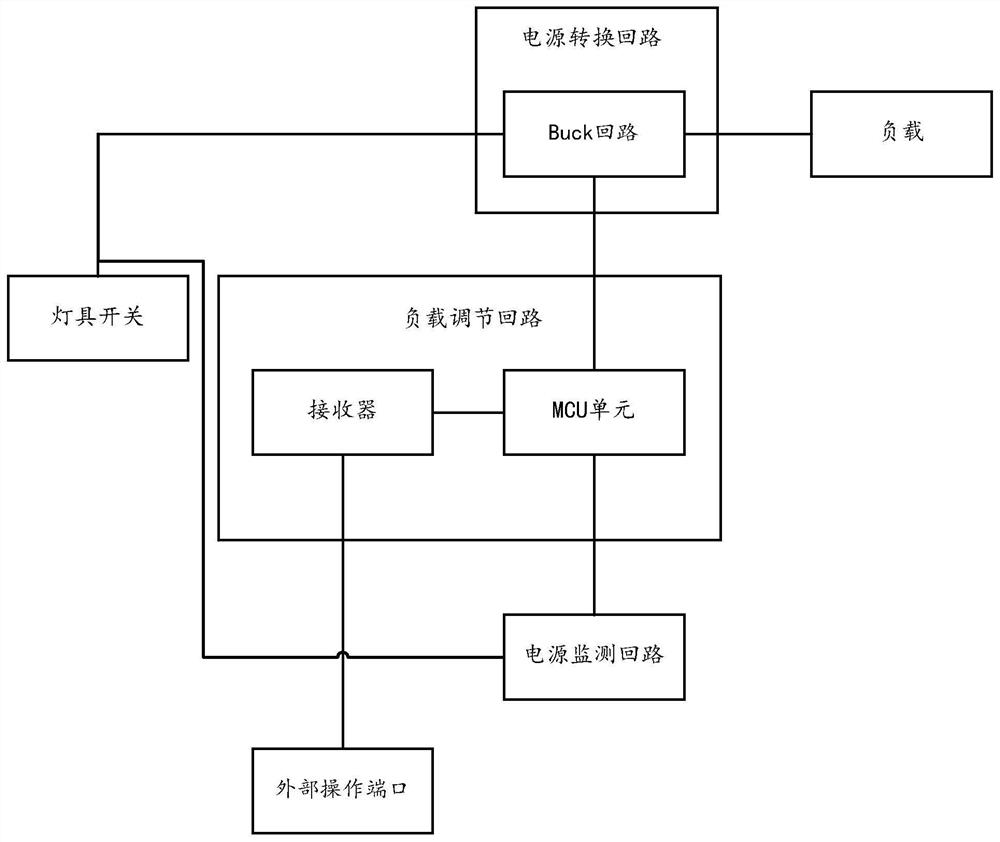
[0061] The third embodiment of the present invention provides a lighting fixture, and the third embodiment is a further improvement of the first or second embodiment; the main improvement is that in the third embodiment of the present invention, see image 3 As shown, the power conversion circuit includes: Buck circuit;
[0062] The MCU unit is electrically connected to the Buck loop, and the Buck loop adjusts the load of the lighting fixture according to the received PWM signal.
[0063] The load connected to the Buck loop can be effectively and conveniently controlled by the PWM signal sent by the MCU unit.
PUM
 Abstract
Description
Claims
Application Information
 - R&D
- Intellectual Property
- Life Sciences
- Materials
- Tech Scout
- Unparalleled Data Quality
- Higher Quality Content
- 60% Fewer Hallucinations
Browse by: Latest US Patents, China's latest patents, Technical Efficacy Thesaurus, Application Domain, Technology Topic, Popular Technical Reports.
© 2025 PatSnap. All rights reserved.Legal|Privacy policy|Modern Slavery Act Transparency Statement|Sitemap|About US| Contact US: help@patsnap.com


