
Elevator device

A technology for elevators and door devices, which is applied in the field of elevators, can solve problems such as door opening resistance of door devices, difficulty in adjusting the structure of the cam mechanism, and the need to increase the height of the top floor of the elevator passage, so as to improve ride comfort, facilitate installation and adjustment, and restrain up and down The effect of vibration

Active Publication Date: 2018-07-31
SHANGHAI MITSUBISHI ELEVATOR CO LTD
View PDF7 Cites 1 Cited by
  • Summary
  • Abstract
  • Description
  • Claims
  • Application Information

AI Technical Summary

Problems solved by technology

[0008] The main problem is that it is necessary to install additional friction damping devices in addition to the roller guide shoes, including electromagnetic actuators and control devices for driving friction parts. The structure is very complicated and the cost is obviously increased; The common practice is to install the friction damping device vertically with the roller guide shoe. It is necessary to review the installation and operation space for the friction damping device on the elevator structure, and it will also increase the requirements for the height of the top floor of the elevator hoistway; in addition , since the friction damping device and the roller guide shoe are not an integrated structure, they need to be installed separately, which involves positioning and adjustment, etc., making installation and debugging more difficult
[0015] 4. The structure of the cam mechanism is difficult to adjust, because it is pushed in place when the car door is opened, and the cam mechanism produces resistance to the opening of the car door
If the design or installation position of the cam mechanism is inaccurate, it may affect the proper opening of the door and cause greater resistance to the opening of the door device
More seriously, it may cause damage to the door motor or even the entire door device
[0016] 5. The structure of the cam mechanism is difficult to adjust, and the adaptability is relatively poor, so it cannot easily deal with different sill gaps, that is, projects with different distances between the car door sill and the landing door sill
[0017] 6. When the car door is closed, the cam mechanism is reset by means of springs, etc. If the spring is aging or fails, the cam mechanism may not be reset in place, so that there is a risk of collision between the car and the inner parts of the hoistway when the car is running
[0018] 7. After the cam mechanism is reset, that is, when it is in the storage position, its main part is still outside the range of the car when viewed from the direction of the car's lifting and running, and may cause hooks on the inner parts of the hoistway when the car is running. risk
[0019] 8. The cam mechanism is set at both ends of the door opening direction of the door device, so only one or two in pairs can be set, and the expandability is poor
[0020] 9. The structure of the cam mechanism is still relatively complicated, not simple enough, and the cost is high

Method used


Image

  • Elevator device
  • Elevator device
  • Elevator device

Examples


Embodiment Construction

[0067] A further description will be given below in conjunction with specific embodiments and drawings.

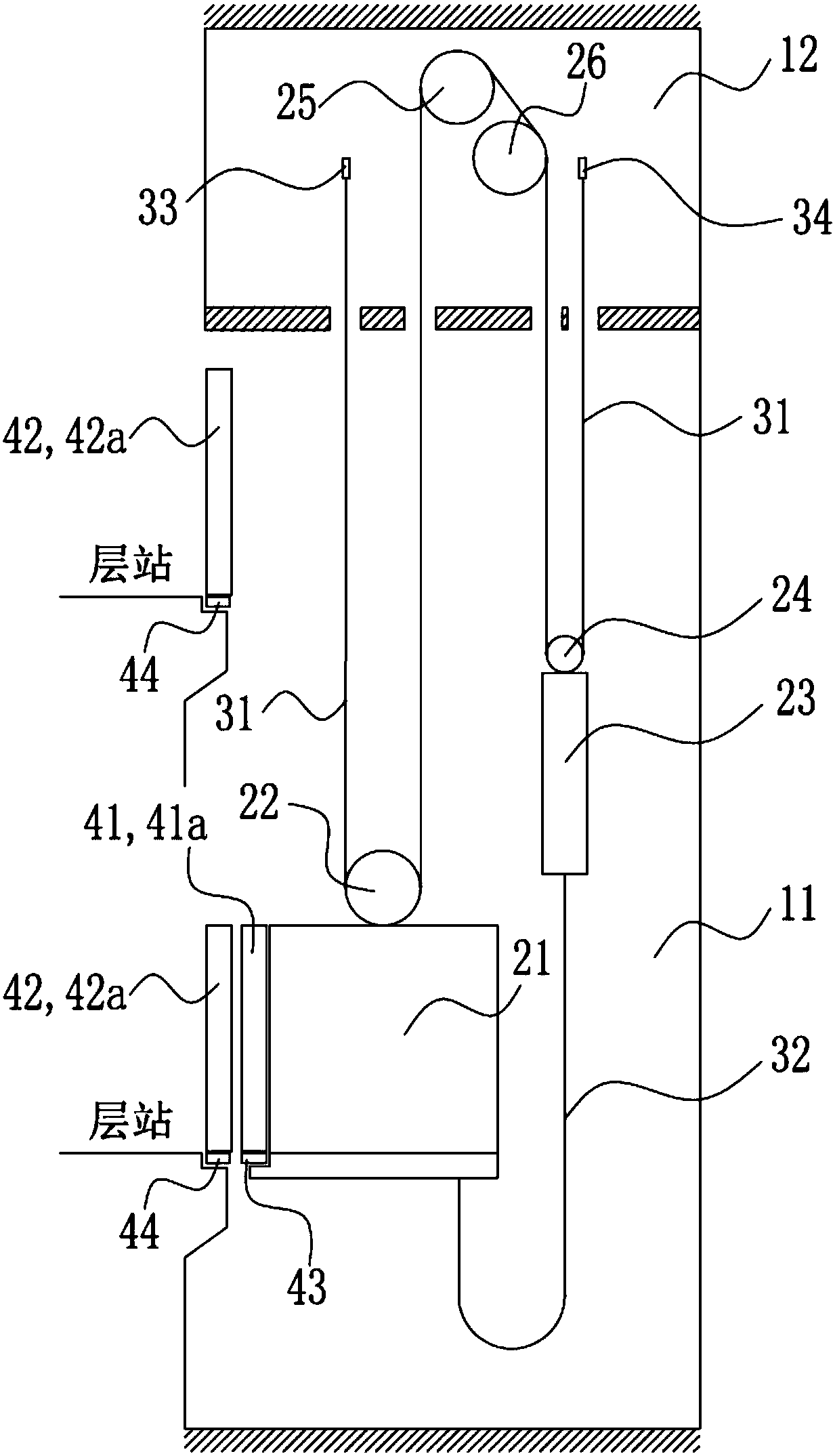
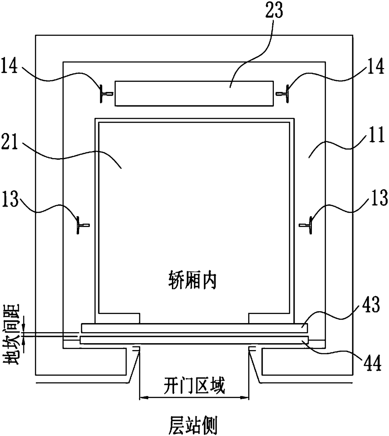
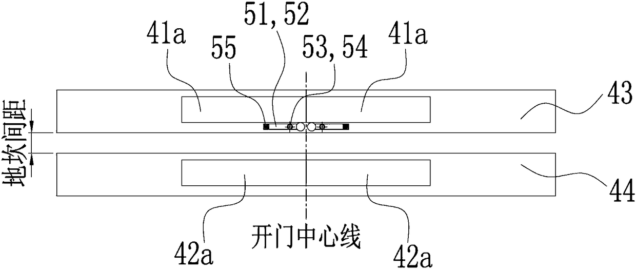
[0068] Such as figure 1 Shown is a schematic diagram of the elevator system. This figure shows the most common elevator with a machine room with a roping ratio of 2:1. In the elevator system, the car 21 and the counterweight 23 are arranged in the hoistway 11, and are respectively guided by the car guide rail and the counterweight guide rail (not shown in this figure). A car-side pulley 22 is provided on the car 21, and a counterweight-side pulley 24 is provided on the counterweight 23. The traction rope 31 bypasses the car-side pulley 22, the driving host 25, the guide pulley 26, and the counterweight-side pulley 24 , The two ends are fixed in the machine room 12 respectively. The traction rope 31 is moved in the vertical direction in the opposite direction in the lifting channel 11 by the driving force of the driving host 25 arranged in the machine room 12.

[0069] A car d...


PUM


Abstract

The invention discloses an elevator device. At least one damping device is arranged on a sill. The damping device is released when a door device is opened, and the damping device reaches a working position under the effect of self driving force and produces friction force which restrains up-down vibration of a car. When the door device is closed, the door device drives the damping device to reacha storage position. When the car is in a flat-layer position opened state, the car will not produce obvious up-down vibration when passengers enter and exit from the car, stability is higher, and rising comfort of the elevator is improved. The damping device has the advantages of being simple in structure, low in cost, small in size, high in reliability, high in universality and the like. Configuration is quite flexible, produced friction force is stable and continuous, installation and overhaul can be directly achieved in the car or the layer standing side, and hooking and collision risks will not be produced to components inside a shaft during operation of the elevator.

Description

Technical field [0001] The invention relates to elevator technology, in particular to an elevator device. Background technique [0002] In the elevator system, the car and the counterweight are arranged in the elevator channel, respectively guided by the car guide rail and the counterweight guide rail, suspended by the traction rope wound on the driving host, and the driving force of the driving host is in the elevator channel Move in the opposite direction to each other in the vertical direction. [0003] The use of roller guide shoes can improve the riding comfort of running elevators. In recent years, in order to improve the comfort of elevator riding, more and more elevators adopt roller guide shoes. However, for elevators equipped with roller guide shoes, the car is in a state of leveling and the door is opened. When passengers enter and exit, the car will vibrate up and down. The main reason is that the load applied to the car changes due to passengers entering and exiting...

Claims


Application Information

Patent Timeline
IPC IPC(8): B66B11/02F16F15/08
CPCB66B11/0266B66B11/0293F16F15/08F16F2222/04
Inventor 李丰
Owner SHANGHAI MITSUBISHI ELEVATOR CO LTD
Learn More