Sound generator

A technology for sound generators and shells, which is applied in the direction of microphones, sensors, electrical components, etc., which can solve the problems of large magnetic field leakage, low audio output efficiency and sound, and reduced force between the electromagnetic field and the fixed magnetic field, etc., to achieve enhanced magnetic field Interaction force, improve output efficiency and sound, and prevent magnetic flux leakage

Pending Publication Date: 2018-07-31
SUZHOU YICHUAN TECH CO LTD
View PDF0 Cites 0 Cited by
  • Summary
  • Abstract
  • Description
  • Claims
  • Application Information

AI Technical Summary

Problems solved by technology

[0004] However, in the receiver with the above structure, the electromagnetic field generated after the coil is energized is formed into an open type through the iron core and the U-shaped pole piece. Therefore, the electromagnetic field leakage is relatively large, that is, the electromagnetic field that actually participates in driving the vibration of the permanent magnet is less, which makes the electromagnetic field The force between the magnetic field and the fixed magnetic field is greatly reduced, and the audio output efficiency and sound are lower

Method used


Image

  • Sound generator
  • Sound generator
  • Sound generator

Examples


Embodiment 1

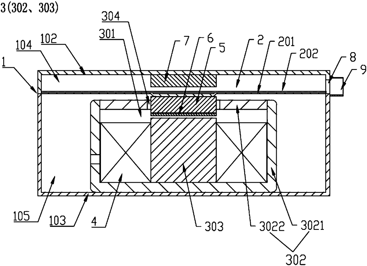
[0059] This embodiment provides a sounder, such as figure 1 As shown, it includes a casing 1 with an installation cavity, and a diaphragm mechanism 2 disposed in the installation cavity. The diaphragm mechanism 2 divides the installation cavity into a first cavity 104 and a second cavity 105 arranged side by side.

[0060] Wherein, the housing 1 includes a first housing 102 and a second housing 103, the first housing 102 is composed of a first bottom surface and a side wall, the second housing 103 is composed of a second bottom surface and a side wall, and the first housing 102 is composed of a first bottom surface and a side wall. 102 is fastened with the second housing 103 to form a hollow installation cavity. A sound hole 8 is disposed on the side wall of the first housing 102 , and a sound guide tube 9 is disposed around the sound hole 8 .

[0061] It should be noted that the installation between the first housing 102 and the second housing 103 is detachable, and the posi...

Embodiment 2

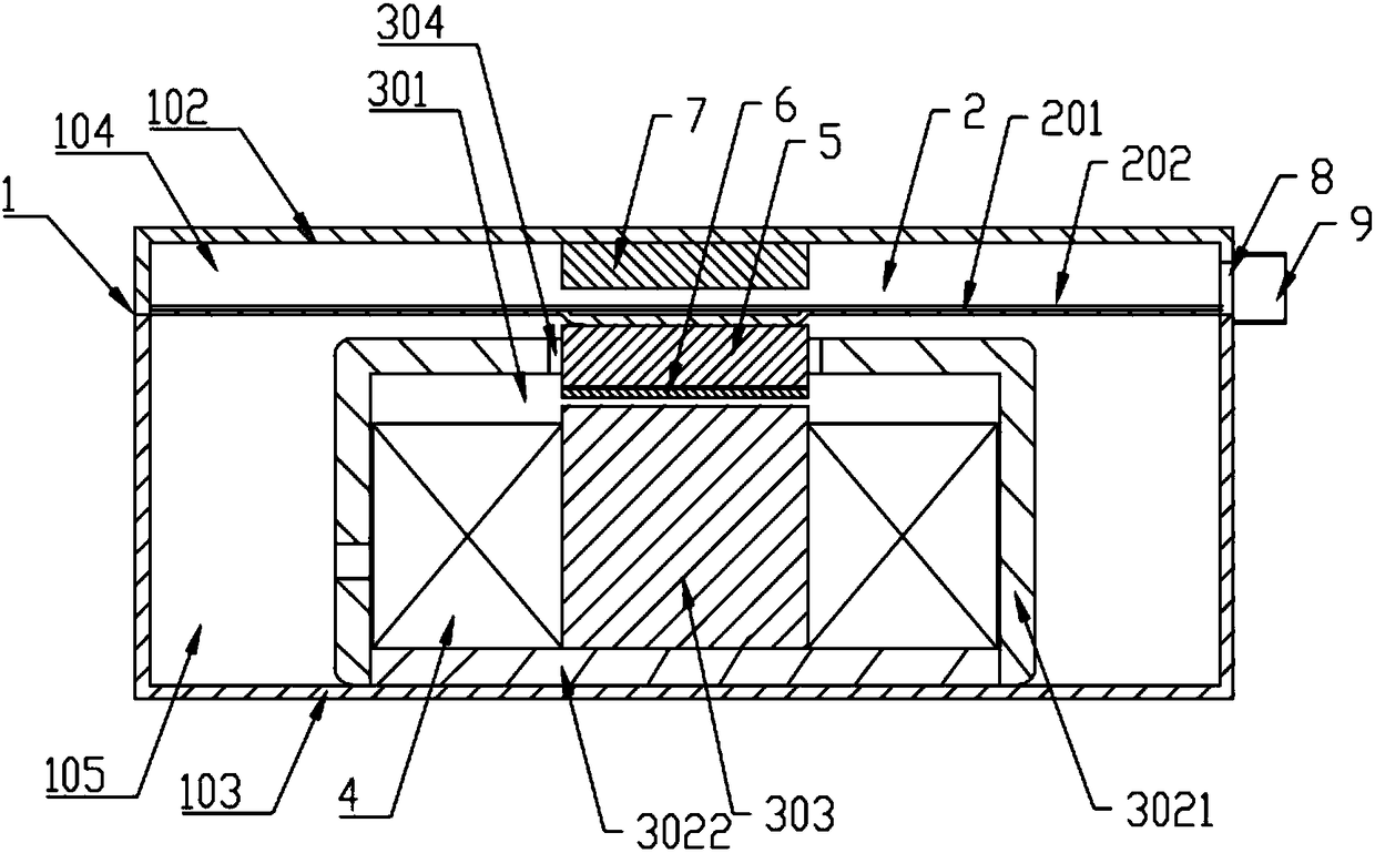
[0094] This embodiment provides a sound generator, which differs from the sound generator provided in Embodiment 1 in that the structure of the hollow cylinder 302 is different.

[0095] Such as figure 2 As shown, in this embodiment, the hollow cylinder 302 includes a cylinder body 3021 and a cover 3022. An opening is provided on the side of the cylinder body 3021 away from the diaphragm mechanism 2, and the cover 3022 is fixed on the opening to close the opening, wherein, The opening can be an open opening or a half-open opening. The constriction opening 304 is opened on the wall surface of the barrel body 3021 near the diaphragm mechanism 2 .

[0096] Compared with the assembling method of the sounder provided in Embodiment 1, the assembling method of the sounder provided in this embodiment differs in that:

[0097] Step S14 , pre-fix the cylinder 303 and the cover 3022 , put the coil on the cylinder 303 , fix the cover 3022 on the opening of the barrel body 3021 to close...

Embodiment 3

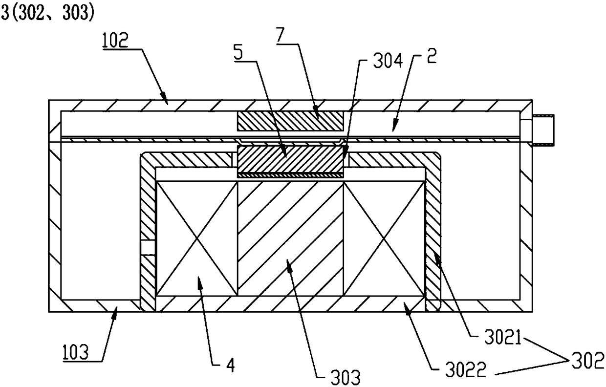
[0099] This embodiment provides a sound generator, which differs from the sound generator provided in Embodiment 1 or Embodiment 2 in that the structure of the second housing 103 is different.

[0100] Such as image 3 As shown, in this embodiment, the bottom of the second housing 103 defines a through hole, and the bottom of the hollow cylinder 302 (ie the side of the hollow cylinder 302 away from the diaphragm mechanism 2 ) is placed in the through hole.

[0101] When the sound generator with this structure is subjected to strong vibration caused by external force, the hollow cylinder 302 and the inner cylinder 303 are not easy to deviate from the center position of the fixed magnetic field, resulting in a decrease in sensitivity, a decrease in sound, and an increase in distortion.

[0102] Compared with the assembling method of the sounder provided in embodiment 1 or embodiment 2, the assembling method of the sounder provided in this embodiment differs in that:

[0103] St...


PUM


Abstract

The invention relates to the technical field of sound production, and discloses a sound generator. The sound generator comprises a shell with a mounting cavity, and a diaphragm mechanism arranged in the mounting cavity, wherein the diaphragm mechanism divides the mounting cavity into a first cavity and a second cavity side by side, characterized in that the sound generator further comprises a limiting component, an electromagnetic component and a magnetic generating component, wherein the limiting component is made of a soft magnetic material, the limiting component is provided with a closed cavity, one side of the closed cavity facing towards the diaphragm mechanism is provided with an opening, and the opening is bent from outside to inside to form a shrinkage opening; the electromagneticcomponent is located in a second cavity and mounted in the closed cavity, and is used for generating an electromagnetic field and transmitting the electromagnetic field to the limiting component; andthe magnetic generating component is fixed on the diaphragm mechanism, extends into the shrinking opening, and is used for providing a fixed magnetic field. According to the scheme of the invention,the electromagnetic field is limited in the closed cavity of the limiting component, the magnetic leakage is not easy to occur, the acting force between the magnetic fields can be enhanced, and thus the output efficiency and sound of audios can be improved.

Description

technical field [0001] The invention relates to the technical field of sound generation, in particular to a sound generator. Background technique [0002] The receiver is a tiny electro-acoustic device that converts audio electrical signals into sound signals without sound leakage, so as to realize audio playback. It is widely used in portable electronic equipment such as mobile phones, notebook computers, earphones, and hearing aids. [0003] With the continuous development of science and technology, the structure of the receiver has also been continuously improved. For example, in an existing receiver, the housing is divided into a first cavity and a second cavity by a diaphragm mechanism, and a U-shaped pole piece is arranged in the second cavity, and a sleeve is installed in the U-shaped pole piece. The iron core of the coil and the side of the diaphragm mechanism close to the second cavity are fixed with a permanent magnet. The working principle of the receiver is tha...

Claims


Application Information

Patent Timeline
Patent Type & Authority Applications(China)
IPC IPC(8): H04R9/08H04R9/02
CPCH04R9/08H04R9/02H04R2410/00
Inventor 陈晓明吴哲
Owner SUZHOU YICHUAN TECH CO LTD
Why Eureka
Try Eureka