
Screen sounding structure, front cover plate, rear cover plate and electronic equipment

A technology of screen sound and front cover, which is applied in the field of rear cover and electronic equipment, front cover, and screen sound structure, and can solve the problem of dual MIC noise reduction performance degradation, Echo processing performance degradation, and poor audio and video playback effects, etc. problem, to achieve the effect of full screen sound, simple structure, and normal display

Pending Publication Date: 2020-11-03
伯恩创盛技术研发(惠州)有限公司
View PDF0 Cites 0 Cited by
  • Summary
  • Abstract
  • Description
  • Claims
  • Application Information

AI Technical Summary

Problems solved by technology

[0005] The content of the invention is to provide a screen sounding structure, front cover, rear cover and electronic equipment, which mainly solves the problem that the existing screen sounding technology adopts the cantilever piezoelectric ceramic scheme and the screen exciter scheme, and a vibration module must be provided. , resulting in the increase of the thickness of the whole machine; and the problems of uneven frequency response, decreased Echo processing performance, decreased noise reduction performance of dual MICs, poor audio and video playback effects, and poor confidentiality of the pass through when the exciter is attached to the middle frame.

Method used


Image

  • Screen sounding structure, front cover plate, rear cover plate and electronic equipment
  • Screen sounding structure, front cover plate, rear cover plate and electronic equipment
  • Screen sounding structure, front cover plate, rear cover plate and electronic equipment

Examples


Embodiment 1

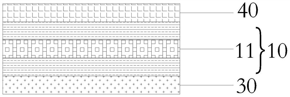
[0031] Such as figure 1 As shown, in order to solve the above problems, this embodiment proposes a screen sound structure, which includes the internal drive circuit of the mobile terminal, and also includes a sequential and stacked front cover support structure 40, ITO piezoelectric film 10 and back cover support Structure 30; conductive lines are formed on both ends of the ITO piezoelectric film 10, and the conductive lines are electrically connected to the internal drive circuit; the ITO piezoelectric film 10 vibrates under the drive of the internal drive circuit, and drives the front cover support structure 40 Or the rear cover support structure 30 resonates and sounds.

[0032] In this embodiment, the ITO piezoelectric film 10 is a film structure, relatively soft, so the front cover support structure 40 or the rear cover support structure 30 mainly provides support for the ITO piezoelectric film 10, and under the premise of ITO vibration , the front cover support structur...

Embodiment 2

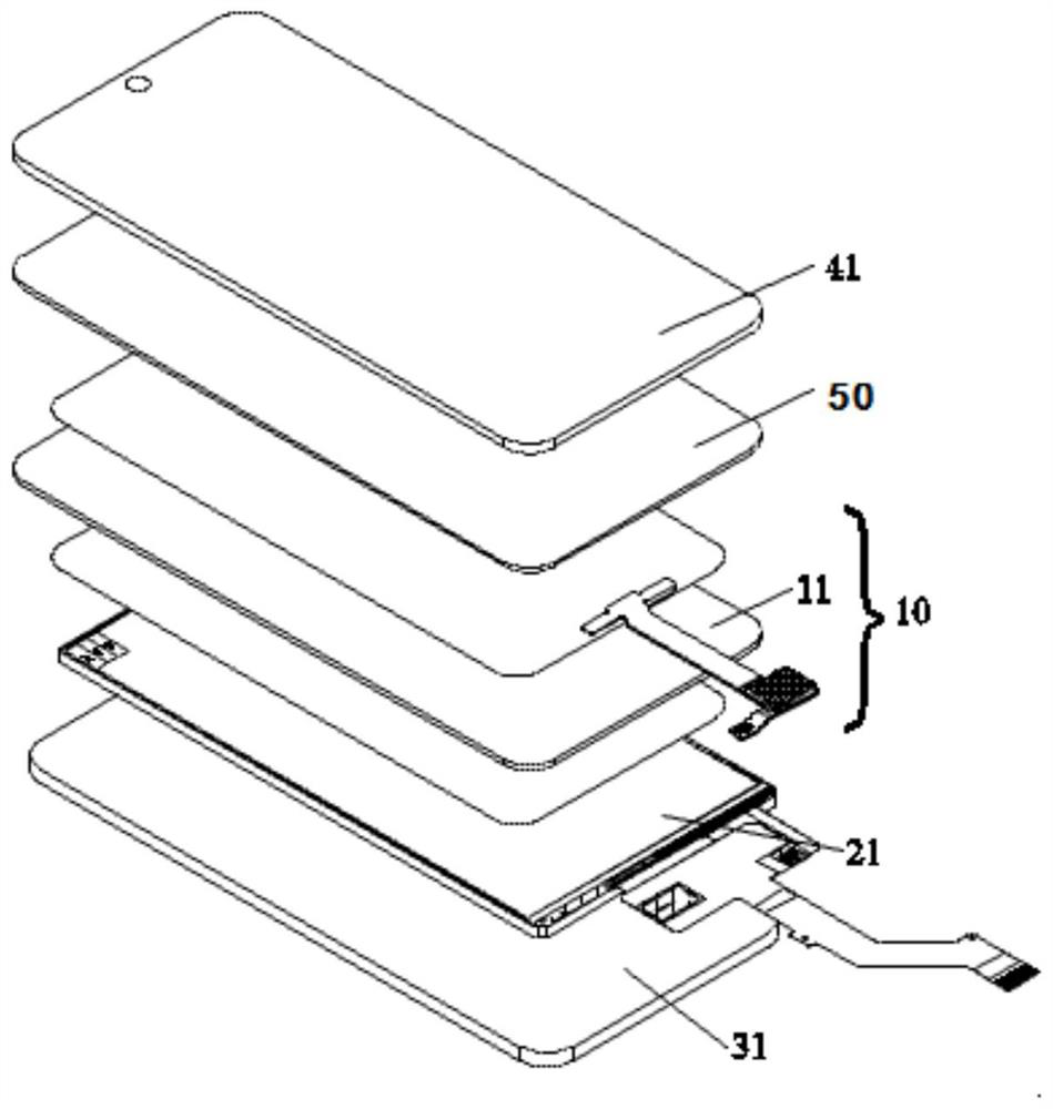
[0036] Such as Figure 2 to Figure 4 As shown, this embodiment proposes a front cover, which includes the internal drive circuit of the mobile terminal, and also includes a front cover support structure 40, an ITO piezoelectric film 10, and a rear cover support structure 30 that are sequentially and stacked; The electrical film 10 is a polyvinylidene fluoride film 11 (hereinafter referred to as PVDF film 11 ) with ITO coating on both sides. The above structure is consistent with that of Embodiment 1, and will be repeated here.

[0037] In this embodiment, the front cover support structure 40 includes a front cover protective glass, and the rear cover support structure 30 includes a complete machine assembly module 30 .

[0038] In this embodiment, the front cover protective glass and the ITO piezoelectric film 10 are bonded by optical glue 50 to ensure the tightness of the bonding between the ITO piezoelectric film 10 and the front cover protective glass, thereby ensuring the...

Embodiment 3

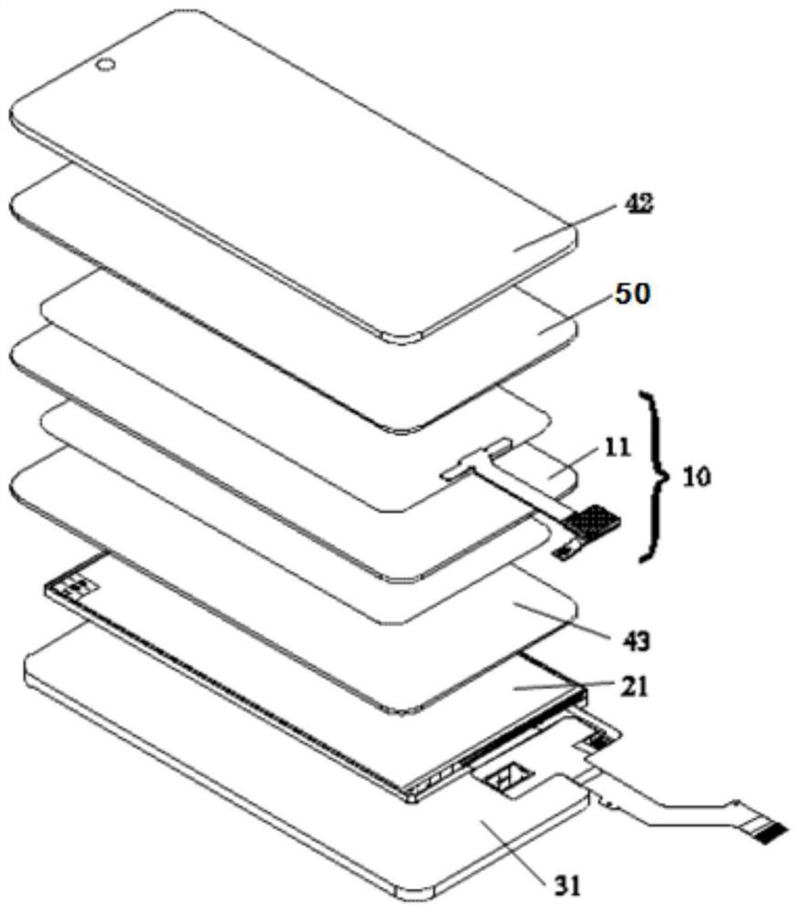
[0043] Such as Figure 5 to Figure 7 As shown, in order to solve the aforementioned problems, this embodiment proposes a rear cover, including an internal drive circuit, a front cover support structure 40, an ITO piezoelectric film 10 and a rear cover support structure 30, and the ITO piezoelectric film 10 is a double For the polyvinylidene fluoride film (hereinafter referred to as PVDF film 11 ) with an ITO coating on its surface, the positional relationship between the above structures is the same as that of Embodiment 1, and will not be repeated here.

[0044] In this embodiment, the front cover support structure 40 is a glass panel, and the rear cover support structure 30 is a rear decorative glass 32 .

[0045] In this embodiment, the ITO piezoelectric film 10 is attached to the rear decorative glass 32 through optical glue 50 . Among them, OCA optical glue 50 is preferably used between the ITO piezoelectric film 10 and the rear decorative glass 32 .

[0046] More speci...


PUM


Abstract

The invention relates to the technical field of screen sound production, in particular to a screen sound production structure, a front cover plate, a rear cover plate and electronic equipment, and thescreen sound production structure comprises an internal driving circuit of a mobile terminal, and a front cover supporting structure, an ITO piezoelectric film and a rear cover supporting structure which are sequentially arranged in a stacked manner; conductive circuits are formed on the end surfaces of the two ends of the ITO piezoelectric film, and are electrically connected with the internal driving circuit; and the ITO piezoelectric film vibrates under the driving of the internal driving circuit and drives the front cover supporting structure or the rear cover supporting structure to resonate and produce sound. According to the invention, the problem that a cantilever piezoelectric ceramic scheme and a screen exciter scheme are adopted in the existing screen sounding technology, and avibration module must be arranged, so the thickness of the whole machine is increased is solved; and the problems of frequency response unevenness, Echo processing performance reduction, dual-MIC noise reduction performance reduction, poor audio-video playing effect and poor communication confidentiality due to the fact that an exciter is attached to a middle frame are solved.

Description

technical field [0001] The invention relates to the technical field of screen sound generation, in particular to a screen sound generation structure, a front cover, a rear cover and electronic equipment. Background technique [0002] The existing mobile phone screen is gradually moving towards borderless and visually limitless, so it is necessary to rearrange the front camera and the earpiece on the top of the mobile phone. Therefore, in order to avoid the design of the earpiece on the top of the mobile phone, the screen sound technology has evolved. [0003] The principle of screen sound technology applied to mobile phones is to use other components of the mobile phone instead of the speaker diaphragm to vibrate to produce sound. At present, the screen sound technology on the market mainly includes the cantilever piezoelectric ceramic scheme and the screen exciter scheme. Among them, the cantilever piezoelectric ceramic scheme uses a drive unit to convert electrical signa...

Claims


Application Information

Patent Timeline
Patent Type & Authority Applications(China)
IPC IPC(8): H04M1/02H04M1/03
CPCH04M1/026H04M1/035
Inventor 宁显伟黄宇正王钰余雅
Owner 伯恩创盛技术研发(惠州)有限公司
Learn More