
Scanning headlight and control method and program for scanning head light

A technology of headlights and control parts, which is applied in the field of scanning headlights

Inactive Publication Date: 2018-07-31
TOPPAN PRINTING CO LTD
View PDF8 Cites 0 Cited by
  • Summary
  • Abstract
  • Description
  • Claims
  • Application Information

AI Technical Summary

Problems solved by technology

For example, Non-Patent Document 1 describes a system that uses an infrared camera installed at the front of the vehicle to obtain images of the traffic environment in front, recognizes pedestrians through image processing, and reflects the presence of pedestrians through sound or display on the car display, thereby causing driver's attention

Method used


Image

  • Scanning headlight and control method and program for scanning head light
  • Scanning headlight and control method and program for scanning head light
  • Scanning headlight and control method and program for scanning head light

Examples


Embodiment approach 1

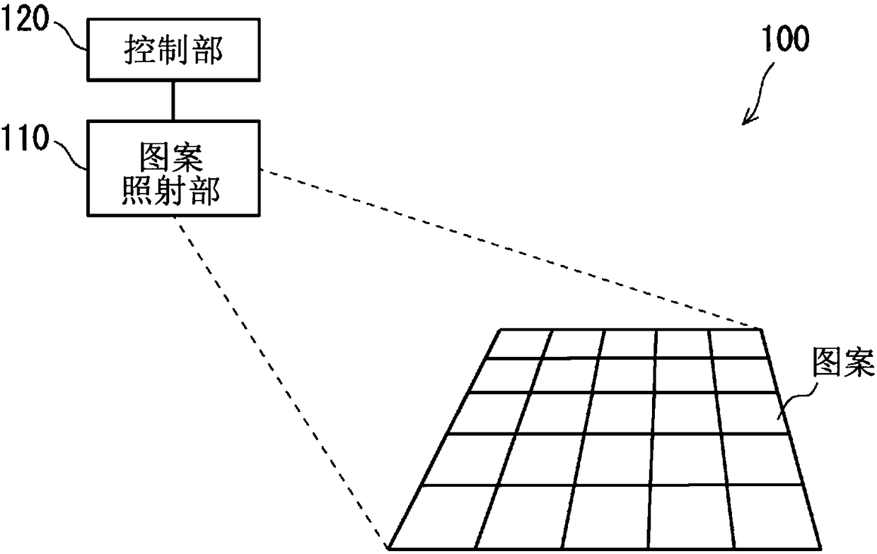
[0022] First, use figure 1 The block diagram of FIG. 2 describes the configuration of the scanning headlight according to Embodiment 1 of the present invention.

[0023] The scanning headlight 100 has a pattern irradiation unit 110 and a control unit 120 .

[0024] The pattern irradiation unit 110 has a function of generating a continuous pattern of visible light (hereinafter referred to as a scanning pattern) and irradiating it to the environment ahead. Typically, the pattern irradiation unit 110 is disposed in or near a headlight unit of an automobile.

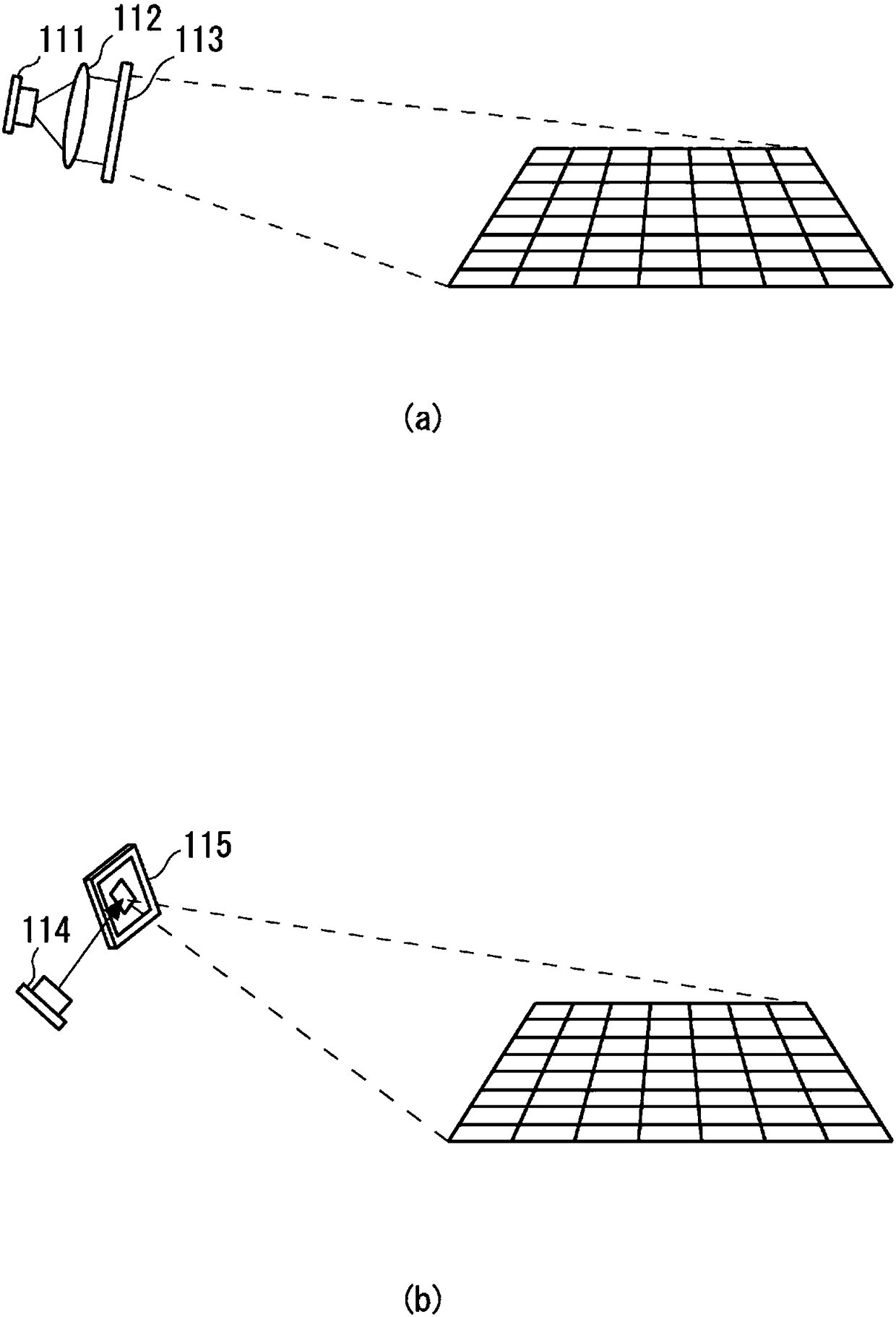
[0025] figure 2 A specific configuration example of the pattern irradiation unit 110 is shown. figure 2 (a) is a configuration example of the pattern irradiation unit 110 using a diffractive optical element (DOE:Differaction Optical Element). The pattern irradiation unit 110 includes a laser element 111 , a lens 112 , and a DOE 113 . The laser element 111 emits laser light. The lens 112 magnifies the laser light into...

Embodiment approach 2

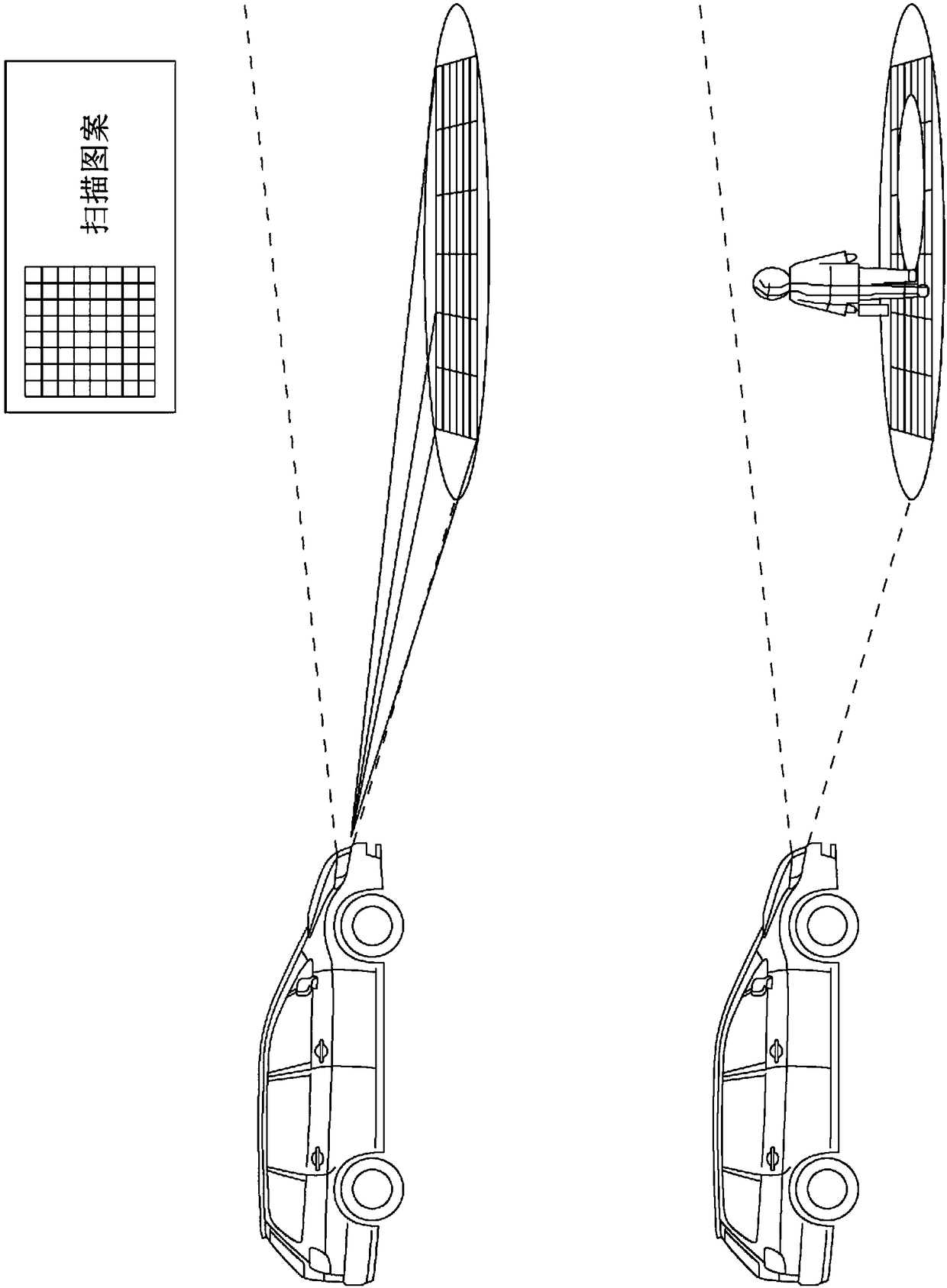
[0038] In Embodiment 2, an example is shown in which instead of simply irradiating the scanning pattern to the front environment, the control unit 120 controls the pattern irradiation unit 110 by changing the irradiation form of the scanning pattern based on various conditions.

[0039] Preferably, the scanning headlight 100 of Embodiment 2 further includes an obstacle detection unit 130 that detects whether there is an obstacle in the environment ahead, and detects its position (for example, direction and distance) if there is an obstacle ( Image 6 ). The rest of the configuration is the same as that of Embodiment 1 unless otherwise mentioned.

[0040] An example of the operation of the scanning headlight 100 according to Embodiment 2 will be described below.

[0041] (a) Control of irradiation timing

[0042] First, the obstacle detection unit 130 detects that there is an obstacle in the environment ahead. For example, as described in Non-Patent Document 1, the method of...


PUM


Abstract

The invention provides a scanning headlight capable of assisting a driver in recognizing a traffic environment ahead more safely, and a control method and a program for the scanning headlight. A scanning headlight (100) has a pattern irradiator (110) that irradiates an environment ahead of a moving body with a continuous pattern of visible light, and a controller (120) that controls the operationof the pattern irradiator (110). When the continuous pattern is irradiated on an obstacle present in the environment ahead of the moving body, a discontinuous pattern is formed in front of the movingbody.

Description

technical field [0001] The present invention relates to a scanning headlight, a control method and a program for scanning the headlight, for example, it relates to an identification assistance technology for the traffic environment ahead. Background technique [0002] In the past, drivers at night had to rely on the illumination of their headlights to visually identify pedestrians. However, it is sometimes difficult to recognize pedestrians from a sufficiently safe distance only by the light of headlights. [0003] Therefore, in recent years, as a nighttime driving assistance technology, a technology for detecting pedestrians using infrared rays or the like, which are invisible light, has been announced. For example, Non-Patent Document 1 describes a system that uses an infrared camera installed at the front of the vehicle to obtain images of the traffic environment in front, recognizes pedestrians through image processing, and reflects the presence of pedestrians through s...

Claims


Application Information

Patent Timeline
Patent Type & Authority Applications(China)
IPC IPC(8): B60Q1/00B60Q1/02G06V10/145
CPCB60Q2400/50B60Q2300/054B60Q2300/056B60Q2300/45F21Y2115/30F21S41/125F21S41/675F21S41/16B60Q1/085G06V20/58G06V10/145
Inventor 代工康宏
Owner TOPPAN PRINTING CO LTD
Learn More