Flat end stop in a sliding sleeve

A technology for engaging sleeves and stoppers, which is applied to clutches, mechanical drive clutches, mechanical equipment, etc., can solve the problems of difficulty in bending into a circle, affecting accuracy, and difficulty in forming, and achieves the effect of improving calibration performance

Active Publication Date: 2018-07-31
SCHAEFFLER TECH AG & CO KG
View PDF19 Cites 0 Cited by
  • Summary
  • Abstract
  • Description
  • Claims
  • Application Information

AI Technical Summary

Problems solved by technology

Such a stop is difficult to form from the base band of the sleeve, since stretching limits are easily reached and the precision of the teeth around the stop is affected
In addition, the joint sleeve made of cut-to-length strips is thus flexurally rigid, so that subsequent bending into a circle is considerably more difficult due to the high stop

Method used


Image

  • Flat end stop in a sliding sleeve
  • Flat end stop in a sliding sleeve
  • Flat end stop in a sliding sleeve

Examples


Embodiment Construction

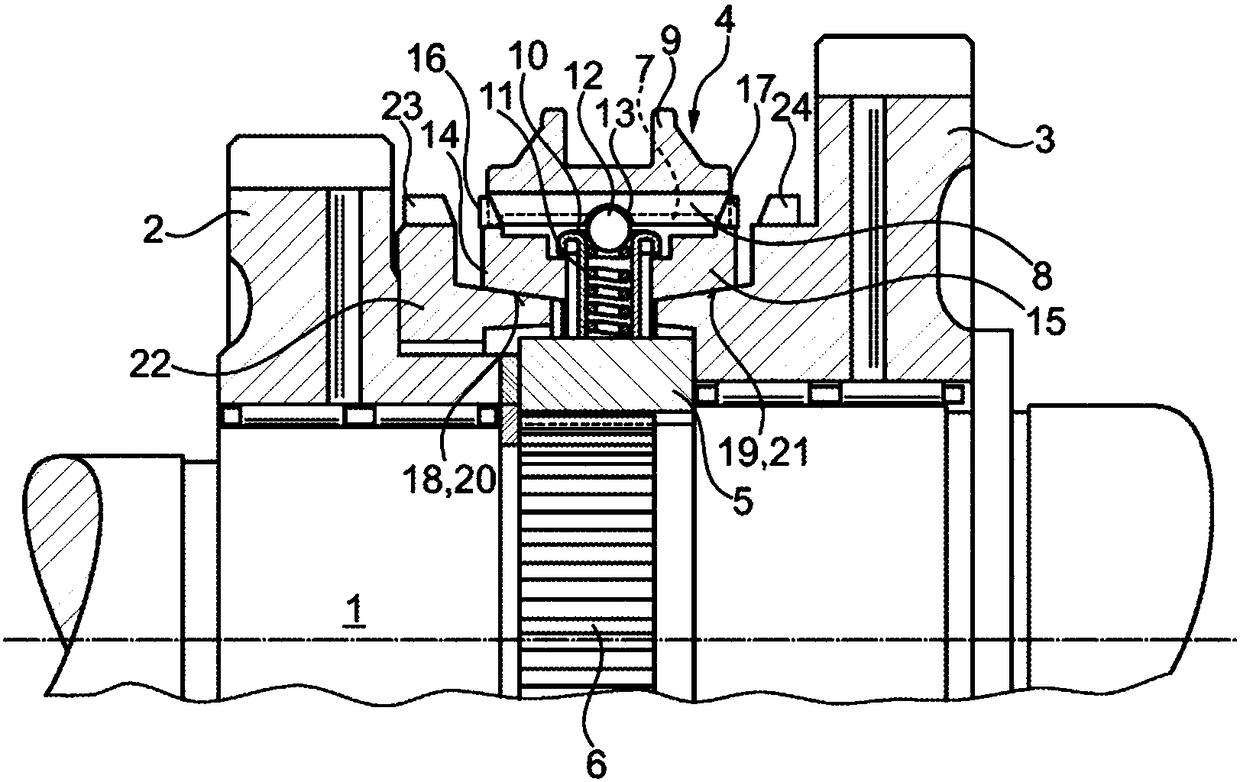
[0019] exist figure 1 Indicated by 1 is a shaft for a gearshift transmission of a motor vehicle on which two gearwheels 2 and 3 are mounted in a freely rotatable manner. Between the two gearwheels 2 and 3 is arranged a synchronization device 4 via which one of the two gearwheels 2 and 3 can be selectively coupled to the shaft 1 . In this way, the shift transmission is switched into different gear stages.

[0020] The synchronization device 4 has a synchronization carrier 5 which engages in a toothing 6 of the shaft 1 in a rotationally fixed manner. Furthermore, the synchronization carrier 5 is provided on its outer circumference with an external toothing 7 into which the teeth 8 of the internal toothing of the clutch sleeve 9 engage. The pressure part 10 is also guided in the synchronization carrier 5 by means of a pressure spring 11 which accommodates a spherical locking element 12 which protrudes from the pressure part 10 in the longitudinal direction. The spherical locki...


PUM


Abstract

In order to limit the shifting path of a sliding sleeve in a synchronizing device of a manual transmission, stops are arranged between the teeth of the internal gear of the sliding sleeve, said stopshaving a height that is smaller than the height of the teeth of the internal gear of the sliding sleeve.

Description

technical field [0001] The invention relates to an end stop for limiting the shifting path of a clutch sleeve, in particular in a synchronizing device of a shift transmission of a motor vehicle. Background technique [0002] Splice sleeves are often used as coupling elements in synchronizers of motor vehicle transmissions. The clutch connects the transmission shaft in a rotationally fixed manner to a gear wheel mounted rotatably on the transmission shaft. Here, the adapter sleeve is positioned concentrically with the transmission shaft on the synchronous carrier Arranged in a rotationally fixed manner, the synchronizing carrier is likewise connected to the transmission shaft in a rotationally fixed manner, and the clutch can be moved into two end positions in the longitudinal direction of the transmission shaft and can be coupled to the gearwheel. The adapter sleeve likewise has a locking mechanism for the locking element, as shown in DE 10 2011 103 780 A1. [0003] On i...

Claims


Application Information

Patent Timeline
IPC IPC(8): F16D23/06
CPCF16D23/06F16D23/0612F16D2023/0618F16D2023/0631F16D2023/0662F16D2023/0668
Inventor 丹尼斯·东森
Owner SCHAEFFLER TECH AG & CO KG
Why Eureka
Try Eureka