
Pressure vessel comprising a load ring, motor vehicle, and method for manufacturing a pressure vessel

A pressure vessel and load ring technology, applied in the field of pressure vessels, can solve problems such as multiple structural spaces

Inactive Publication Date: 2018-07-31
BAYERISCHE MOTOREN WERKE AG
View PDF5 Cites 2 Cited by
  • Summary
  • Abstract
  • Description
  • Claims
  • Application Information

AI Technical Summary

Problems solved by technology

Such a structural design requires more structural space
Furthermore, it (this structural design) cannot transmit forces and moments from one end of the pressure vessel to the other end of the pressure vessel

Method used


Image

  • Pressure vessel comprising a load ring, motor vehicle, and method for manufacturing a pressure vessel
  • Pressure vessel comprising a load ring, motor vehicle, and method for manufacturing a pressure vessel
  • Pressure vessel comprising a load ring, motor vehicle, and method for manufacturing a pressure vessel

Examples


Embodiment Construction

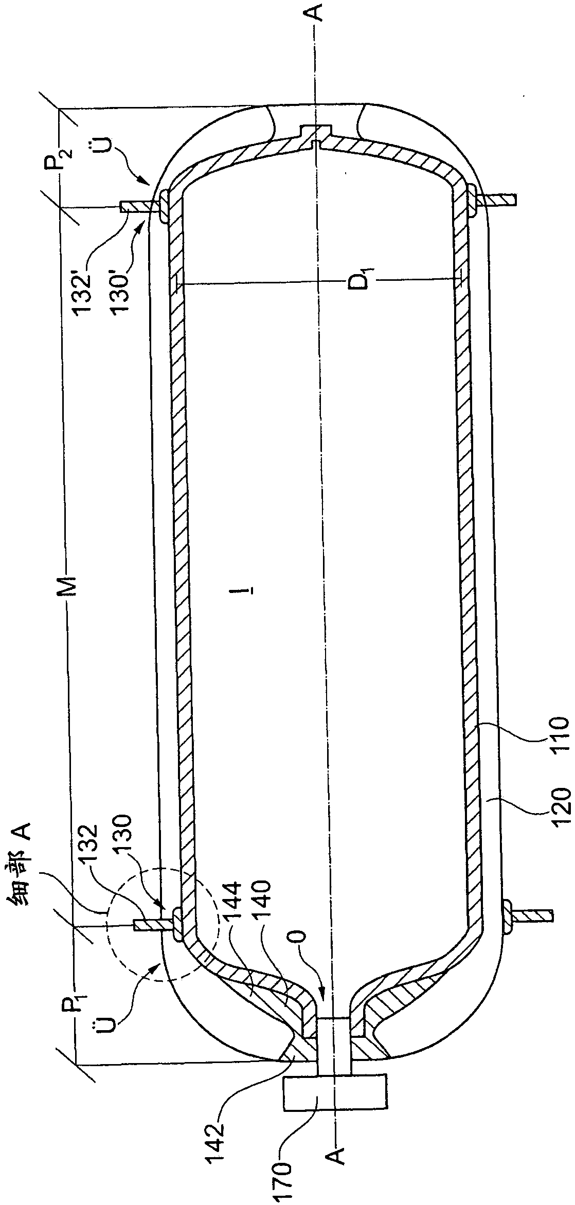
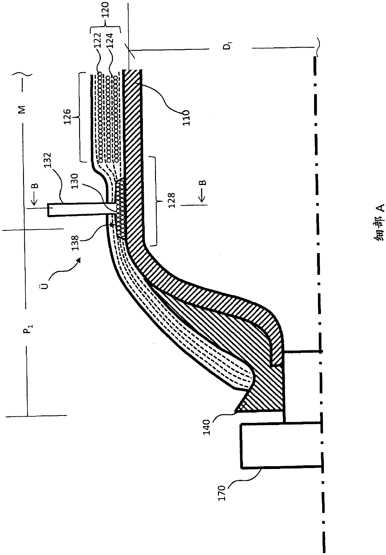
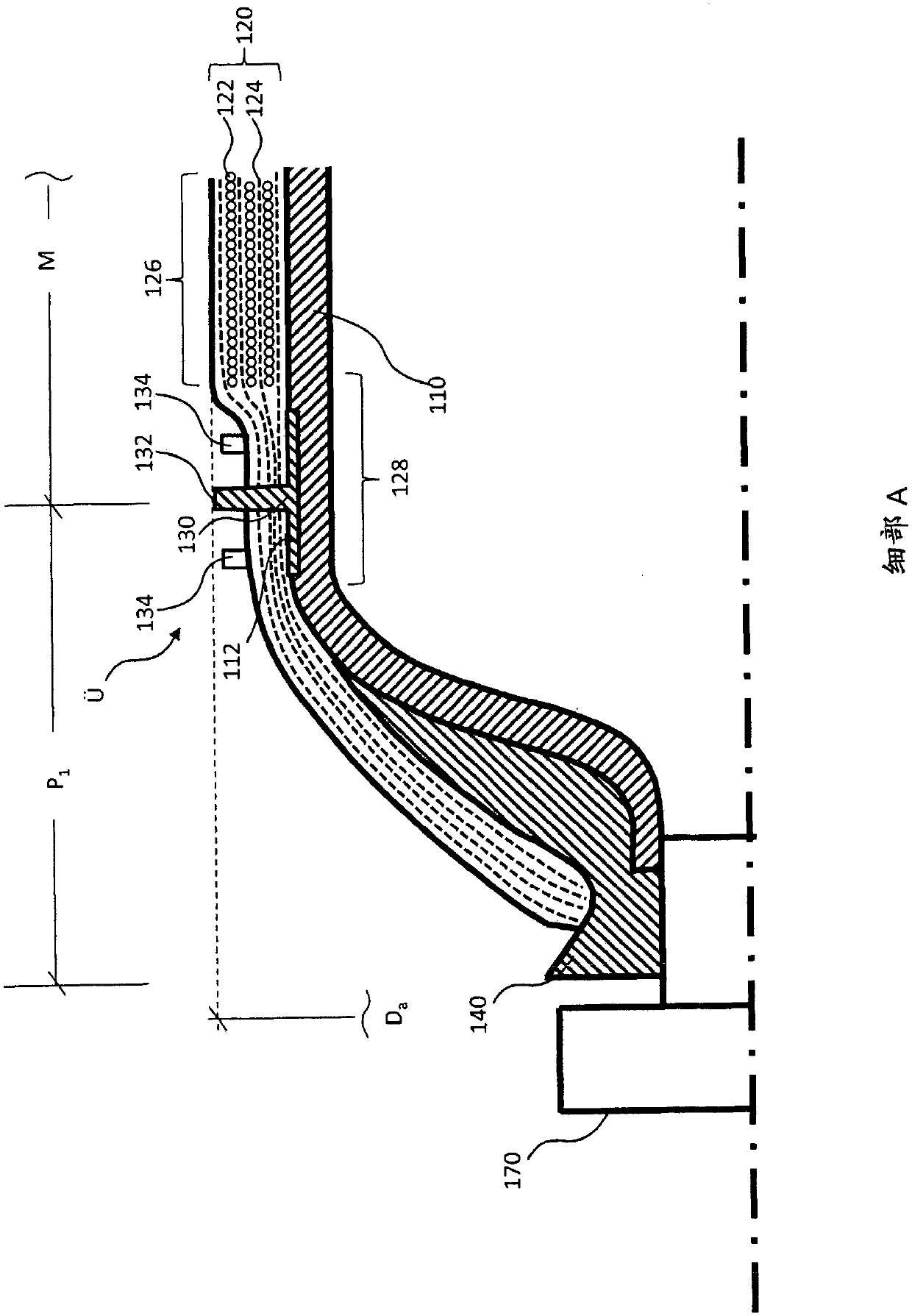
[0040] figure 1 A partial cross-sectional view of a pressure vessel is shown having a liner 110 and a fiber reinforced layer 120 . The inner bladder 110 forms a storage volume 1 for fuel. at the front end P 1 An outlet or hole O for stored fuel is provided on the top. The hole O and the flange 140 cannot be regarded as the connecting pin 132 . Connecting pin 132 is connected from surface 138 of load ring 130 (see Figure 5 ) raised. The connecting pin 132 may have a bearing reinforcement (not shown) at the foot of the connecting pin 132 . The connecting pin 32 is formed in one piece here with the load ring 130 , which bears directly on the inner container 110 here. The load ring 130 protrudes here into the lateral peripheral region M of the pressure vessel or of the inner container 110 . The load ring 130 is here completely covered by the fiber-reinforced layer 120 . Only the connection pins 132 protrude from the fiber-reinforced layer 120 . The protruding portion of ...


PUM


Abstract

The technology disclosed herein relates to a pressure vessel for storing fuel. Said pressure vessel comprises a liner (110) for storing fuel, a fiber-reinforced layer (120) that surrounds at least some areas of the liner (110), and at least one load ring (130, 130'). Connection pins (132, 132') project from the surface (138) of the load ring (130, 130'), the connection pins (132, 132') protrudingfrom the fiber-reinforced layer (120). The technology disclosed herein further relates to a motor vehicle and a method for manufacturing a pressure vessel of said type.

Description

technical field [0001] The technology disclosed here relates to a pressure vessel with a load ring, a motor vehicle and a method for producing a pressure vessel. Background technique [0002] A pressure vessel expands based on factors such as internal pressure p or temperature T of the pressure vessel. For this reason, the pressure vessel is connected to the body of the motor vehicle according to the fixed bearing-floating bearing principle (Festlager-Loslager-Prinzip). Such a structural design requires more structural space. Furthermore, it (this structural design) cannot transmit forces and moments from one end of the pressure vessel to the other end of the pressure vessel. It (this structural design) therefore does not contribute or only slightly contributes to the rigidity of the vehicle body. [0003] A cylinder for pressurized gas is known from DE 1993551 6A1, which cylinder has a support ring flange on its respective end. Furthermore, DE 10 2010 053874 A1 disclose...

Claims


Application Information

Patent Timeline
Patent Type & Authority Applications(China)
IPC IPC(8): F17C13/08
CPCF17C2205/0192F17C1/06F17C13/083F17C2201/0109F17C2201/056F17C2203/012F17C2203/0604F17C2203/0617F17C2203/0619F17C2203/0646F17C2203/066F17C2203/0663F17C2221/012F17C2221/033F17C2223/0115F17C2223/0123F17C2223/0161F17C2223/033F17C2223/035F17C2223/036F17C2270/0168Y02E60/32F17C1/005F17C1/08F17C2203/0626F17C2209/2154F17C2209/234F17C2270/0184
Inventor T·克里斯特O·库西格纳
Owner BAYERISCHE MOTOREN WERKE AG
Learn More