Scraping knife mechanism of centrifugal machine

A centrifuge and scraper technology, applied in the direction of centrifuge, etc., can solve the problems of affecting the normal operation of the centrifuge, affecting the subsequent use, and damage to the scraper assembly, so as to shorten the clearing time and improve work efficiency.

Active Publication Date: 2018-08-03
ZHANGJIAGANG ZHONGNAN CHEM MACHINERY
View PDF10 Cites 0 Cited by
  • Summary
  • Abstract
  • Description
  • Claims
  • Application Information

AI Technical Summary

Problems solved by technology

If the ordinary scraper suddenly descends due to misoperation during the centrifugation process, the material will impact the scraper at high speed, which may cause damage to the scraper assembly, and may also cause vibration of the centrifuge due to uneven internal materials, affecting the normal operation of the centrifuge; and the centrifuge During transportation, since the scraper has a degree of freedom in the vertical direction, the scraper assembly may move up and down due to bumps and affect subsequent use, or the scraper may fall under the action of gravity, which may cause damage to the inner parts of the drum

Method used


Image

  • Scraping knife mechanism of centrifugal machine
  • Scraping knife mechanism of centrifugal machine
  • Scraping knife mechanism of centrifugal machine

Examples


Embodiment Construction

[0022] Specific embodiments of the present invention will be described in detail below in conjunction with the accompanying drawings.

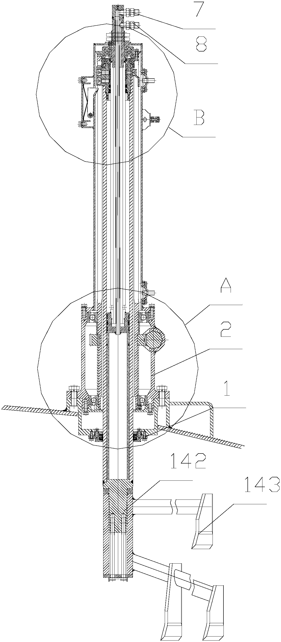
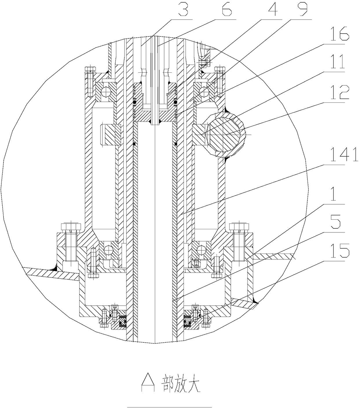
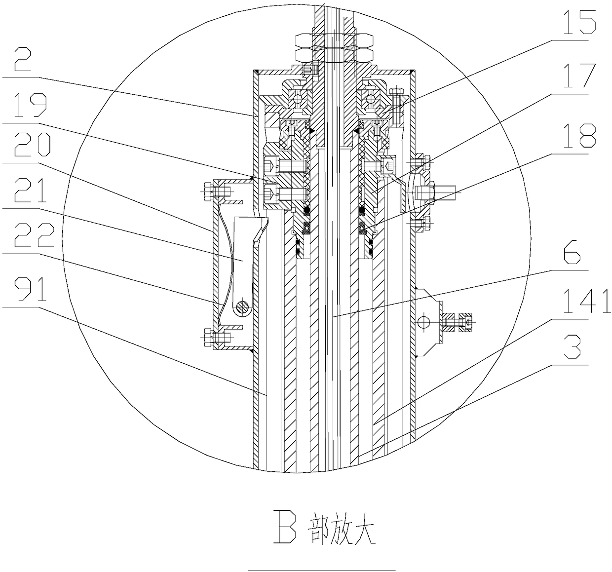
[0023] Such as Figure 1-5 As shown, a centrifuge scraper mechanism includes a connecting seat 1 connected to the top cover of the centrifuge and the middle part runs through the longitudinal direction. The connecting seat 1 is provided with a cylindrical mounting seat 2 with one end closed, and the center of the cylindrical mounting seat 2 is along the shaft. A hydraulic assembly is installed in the direction of the piercing, and the hydraulic assembly includes a knife-receiving oil pipe 3 pierced in the center of the cylindrical mounting seat 2, a spacer 4 arranged at the bottom of the knife-receiving oil pipe 3 in turn, and a positioning pipe 5, and the lower end of the positioning pipe 5 passes through the connecting seat 1. The cutting oil pipe 3 is pierced with a knife feeding oil pipe 6, the lower end of the knife feeding oil pipe 6 pas...


PUM


Abstract

The invention discloses a scraping knife mechanism of a centrifugal machine, and the scraping knife mechanism can prevent a condition that a scraping knife is trigged by misoperation to move, and is safe to use. The scraping knife mechanism comprises a connecting base connected with the top cover of the centrifugal machine, wherein a barrel-shaped mounting base is arranged on the connecting base;a hydraulic assembly is arranged in the barrel-shaped mounting base in a penetrating mode; the hydraulic assembly comprises a knife collecting oil tube, a spacer bush and a positioning tube; a drive gear is arranged on the guide sleeve; a drive rack matched with the drive gear is arranged in the connecting base; a feeding assembly is movably arranged on the hydraulic assembly; the feeding assemblycomprises a movable sleeve; the bottom end of the movable sleeve is equipped with a scraping knife assembly; a sealing sleeve which is matched with the knife collecting oil tube is arranged at the top end of the movable sleeve; a positioning block is arranged at the periphery of the sealing sleeve; a longitudinal slot hole is formed in the guide sleeve; a mounting box is arranged on the side wallof the barrel-shaped mounting base; a limiting block is hinged in the mounting box; a limiting bump is arranged on the limiting block; an avoiding hole matched with the limiting bump is formed in theside wall of the barrel-shaped mounting base; and a limiting spring for enabling the limiting block to abut against the lower surface of the positioning block is arranged in the mounting box.

Description

technical field [0001] The invention relates to a centrifuge scraper mechanism. Background technique [0002] The scraper in the centrifuge moves up and down in the drum during work to scrape off the remaining material on the filter bag wall after centrifugal filtration. When the centrifuge is working, the scraper moves up to the top of the drum, and the scraper rotates a certain The angle is disengaged from the filter bag wall. If the ordinary scraper suddenly descends due to misoperation during the centrifugation process, the material will impact the scraper at high speed, which may cause damage to the scraper assembly, and may also cause vibration of the centrifuge due to uneven internal materials, affecting the normal operation of the centrifuge; and the centrifuge During transportation, since the scraper has a degree of freedom in the vertical direction, the scraper assembly may move up and down due to bumps and affect subsequent use, or the scraper may fall under the ...

Claims


Application Information

Patent Timeline
Patent Type & Authority Applications(China)
IPC IPC(8): B04B11/08
CPCB04B11/08B04B2011/086B04B2011/088
Inventor 刘鑫彦
Owner ZHANGJIAGANG ZHONGNAN CHEM MACHINERY
Why Eureka
Try Eureka