Lock for security door

A safety door and lock technology, applied in the field of safety doors, can solve the problems of incompatibility, safety hazards, damage to the electromagnet core, etc., and achieve the effect of simplifying the assembly method

Active Publication Date: 2018-08-03
宁波盛威卓越安全设备有限公司
View PDF5 Cites 3 Cited by
  • Summary
  • Abstract
  • Description
  • Claims
  • Application Information

AI Technical Summary

Problems solved by technology

That is to say, the existing lock structure can only adapt to handles with one rotation angle, which cannot be used in common with each other, and has not formed modularization. Different locks need to be designed according to different requirements.
[0005] The electromagnet cores used in the electronic locks of traditional electronic safes are all in direct contact with the side slide, and the handle is directly connected to the paddle, so when the handle rotates, it must have a tendency to drive the paddle to rotate. In this case, Once the handle is turned too hard, the pick will drive the side slide to hit the electromagnet core, damaging the electromagnet core, causing damage to the safe, or causing the side slide to slide directly over the electromagnet core, causing the door to open, causing a safety hazard

Method used


Image

  • Lock for security door
  • Lock for security door
  • Lock for security door

Examples


Embodiment Construction

[0032] The present invention will be further described in detail below in conjunction with the accompanying drawings and embodiments.

[0033] Such as Figure 1-10 Shown is a preferred embodiment of the present invention.

[0034] A lockset for a safety door, characterized in that: comprising

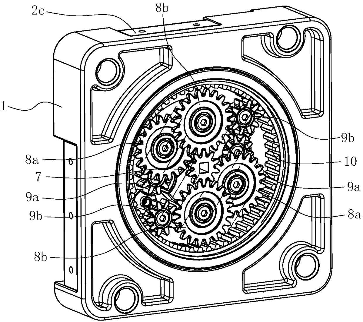
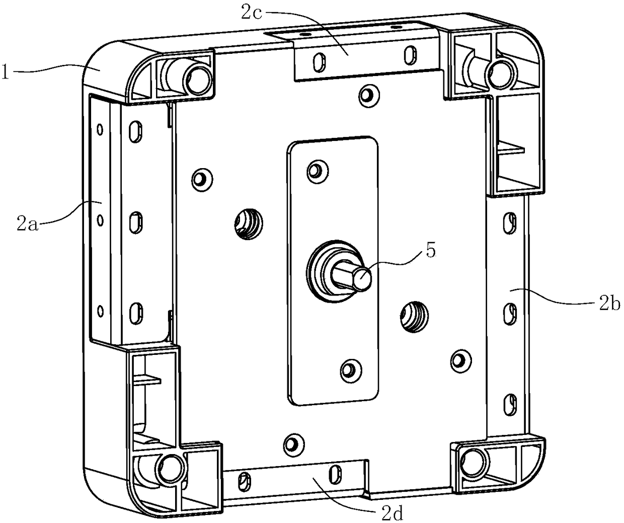
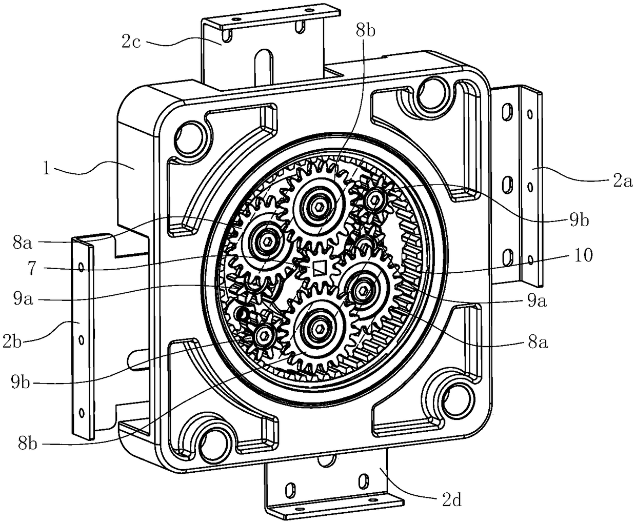
[0035]The lock housing 1 has an accommodating cavity 11 on its front, and the upper cover of the accommodating cavity 11 is provided with a cover plate 12, the cover plate 12 adopts a transparent plate, the bottom surface of the accommodating cavity 11 is provided with a perforation 13, and the accommodating cavity 13 has a The mounting frame 14 is provided with a mounting shaft 15, and the mounting shaft 15 passes through the perforation 13 and reveals the back side of the lock housing 1.

[0036] The left slide plate 2a and the right slide plate 2b are constrained on the back side of the lock housing 1 and can only slide left and right. The left slide plate 2a has a left rack portio...


PUM


Abstract

The invention relates to a lock for a security door. The lock is characterized by comprising a lock shell with a containing cavity, a left sliding plate, a right sliding plate, an output gear, a clutch gear, a handle shaft and a speed reduction gear set. A mounting frame with a mounting shaft is arranged in the containing cavity, the left sliding plate and the right sliding plate are restrained onthe back face of the lock shell, a left rack part is arranged on the left sliding plate, a right rack part is arranged on the right sliding plate, the output gear is arranged on the mounting shaft ina sleeving manner, exposed out of the back face of the lock shell, and engaged with the left rack part and the right rack part in a transmission mode; the clutch gear is arranged on the mounting shaft in a sleeving manner and exposed in the containing cavity, and a clutch structure is arranged between end faces, close to each other, of the clutch gear and the output gear, the handle shaft is movably inserted in a shaft hole of the mounting shaft from the back face of the lock shell, the speed reduction gear set is arranged in the containing cavity, and the handle shaft is in transmission connection with the clutch gear through the speed reduction gear set. The lock for the security door is modular, the lock is suitable for a small-angle rotating handle, and also suitable for a 360-degreerotating handle, in addition, when a lawbreaker forcefully rotates the handle, the handle can idle, and safety is better.

Description

technical field [0001] The invention relates to a lockset suitable for various safety doors, which may be safety doors of safes, safes, gun cabinets or vaults. Background technique [0002] Its structure of traditional safe (cabinet) mainly comprises the casing that has door frame, matches with casing and is connected on the door frame on the door frame by pivot pin, and the latch mechanism that can lock door frame and door frame together. The traditional latch structure includes a slide plate arranged on the back of the door panel, a front latch head fixed to the front end of the slide plate, and a drive mechanism for driving the slide plate to move laterally. In order to enhance the locking reliability of the latch mechanism, some latch mechanisms are also equipped with upper and lower plates, and upper and lower latch heads linked with the upper and lower plates. As it moves up and down, this latch mechanism can not only lock the door panel at the front side, but also lo...

Claims


Application Information

Patent Timeline
Patent Type & Authority Applications(China)
IPC IPC(8): E05B15/00E05B65/52
CPCE05B15/00E05B65/0075
Inventor 陈莉丽姚登仁张波
Owner 宁波盛威卓越安全设备有限公司
Why Eureka
Try Eureka