
Mobile phone screen and manufacturing method thereof

A manufacturing method and technology of mobile phone screens, which are applied in the fields of telephone structure, optics, telephone communication, etc., can solve the problems of reducing user experience satisfaction, increasing light loss and reflection, and reducing color contrast, so as to improve experience satisfaction, improve Contrast, inexpensive effects

Pending Publication Date: 2018-08-03
JIANGXI HOLITECH TECH
View PDF2 Cites 0 Cited by
  • Summary
  • Abstract
  • Description
  • Claims
  • Application Information

AI Technical Summary

Problems solved by technology

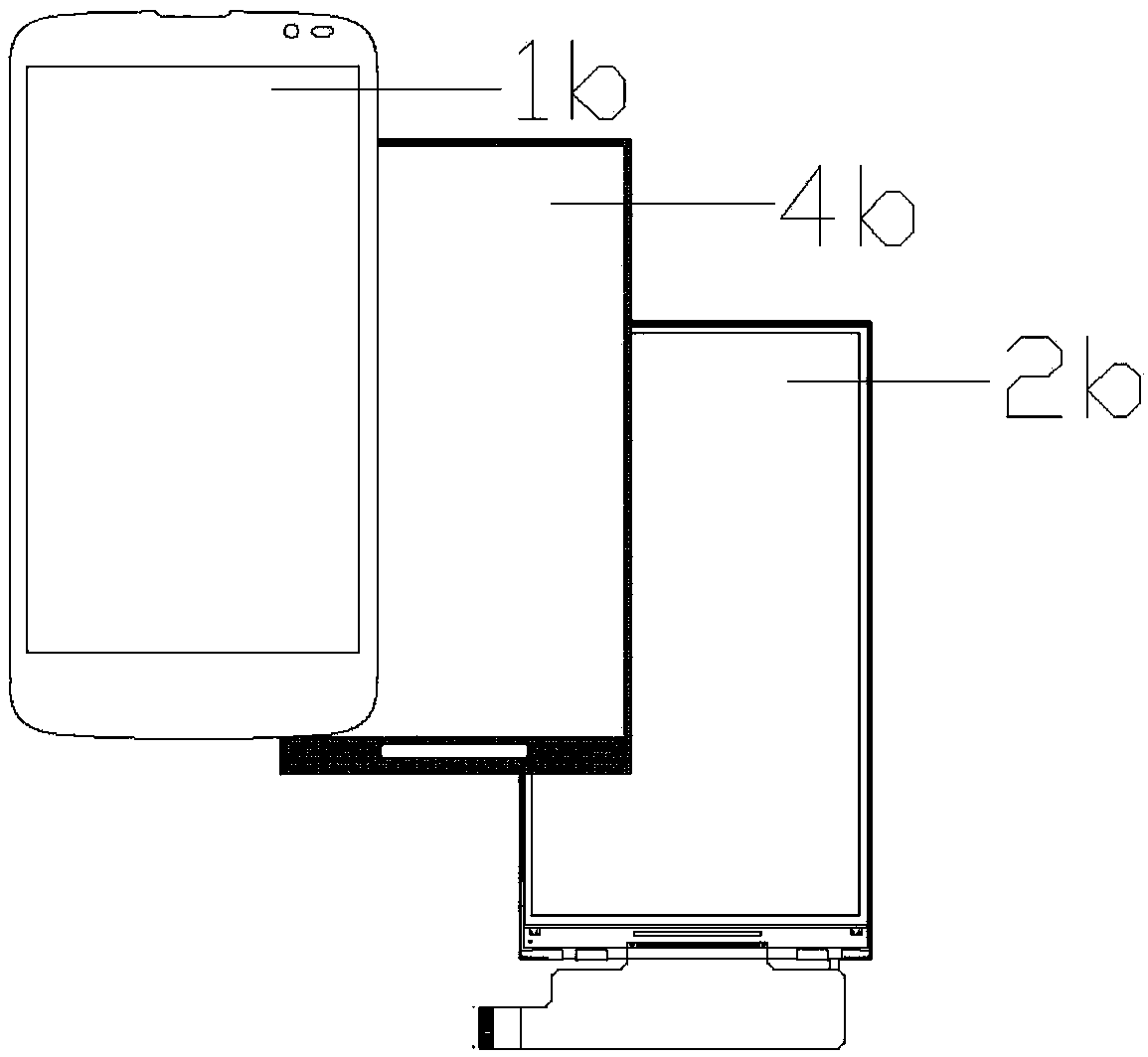
[0003] However, the mobile phone screen formed by adopting the above-mentioned foam bonding scheme has the following technical problems: since the inside of the foam 4b is hollowed out, there will be an air medium layer between the upper polarizer 3b and the touch screen 1b, according to the principle of liquid crystal display , the display image seen by the human eye is actually formed by polarized light filtered by the upper polarizer 3b, and the presence of an air medium layer between the upper polarizer 3b and the touch screen 1b will increase the loss and reflection of light and reduce the contrast of colors. At the same time, a swimming pool effect will be formed, that is, the display screen sinks, and there is a sense of distance, which reduces the user experience satisfaction

Method used


Image

  • Mobile phone screen and manufacturing method thereof
  • Mobile phone screen and manufacturing method thereof
  • Mobile phone screen and manufacturing method thereof

Examples


Embodiment 1

[0033] A mobile phone screen, comprising a touch screen 1 and a display screen 2, the display screen 2 includes an upper polarizer 3 and an LCD, the LCD includes a CF substrate 4 and a TFT substrate 5, the upper polarizer 3 is glued on one side, the The glued side of the upper polarizer 3 is bonded to the touch screen 1, and the non-glued side of the upper polarizer 3 is bonded to the CF substrate 4 of the LCD through the foam 6. In order to avoid the display area, the foam 6 6 is hollowed out in the shape of a square, and is in contact with the upper polarizer 3 and the CF substrate 4 only through the surrounding edges.

[0034] In the mobile phone screen of the present invention, the glued side of the upper polarizer 3 is bonded to the touch screen 1, so that there is no air medium layer between the upper polarizer 3 and the touch screen 1. According to the principle of liquid crystal display, the displayed image seen by the human eye is actually It is formed by the polarize...

Embodiment 2

[0041] A method for manufacturing a mobile phone screen, comprising the following steps:

[0042] (1) Provide an upper polarizer 3 with glue on one side, and the incoming angle deviation of the upper polarizer 3 is controlled within ±0.5°;

[0043] (2) The glued side of the upper polarizer 3 is bonded to the touch screen 1, and the angle deviation between the upper polarizer 3 and the touch screen 1 is controlled within ±0.5°;

[0044] (3) The touch screen 1 is bonded to the CF substrate 4 of the LCD through the foam 6 arranged on the non-adhesive side of the upper polarizer 3, and the deviation of the bonding angle between the touch screen 1 and the LCD is controlled within ±0.5°, and The deviation of the bonding angle between the upper polarizer 3 and the LCD after the final bonding is controlled within ±2°.

[0045] In the mobile phone screen of the present invention, the glued side of the upper polarizer 3 is bonded to the touch screen 1, so that there is no air medium la...


PUM

PropertyMeasurementUnit
thicknessaaaaaaaaaa

Abstract

The invention discloses a mobile phone screen. The mobile phone screen comprises a touch screen and a display screen; the display screen comprises an upper polarizer and an LCD; the LCD comprises a CFsubstrate and a TFT substrate, and adhesive is arranged on one surface of the upper polarizer; the mobile phone screen is characterized in that the adhesive surface of the upper polarizer is in lamination with the touch screen, and another non-adhesive surface of the upper polarizer is in lamination with the CF substrate of the LCD through foam; and the internal of the foam is hollowed out to form a square shape. The mobile phone screen is low in cost and can approach to an OCA full-lamination display effect. The invention further provides a manufacturing method of the mobile phone screen which is low in cost and can approach to the OCA full-lamination display effect.

Description

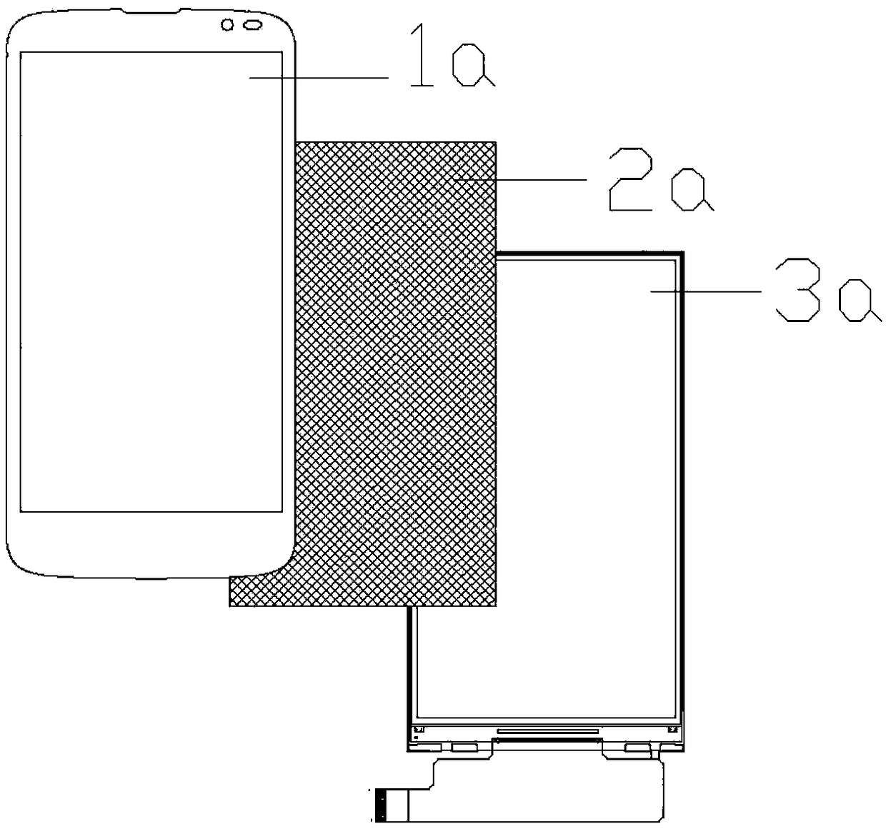
technical field [0001] The invention relates to the technical field of mobile phones, in particular to a mobile phone screen and a manufacturing method thereof. Background technique [0002] Existing mobile phone touch screens and display screens are usually bonded in two ways: one is to use OCA full bonding, such as figure 1 As shown, it includes a touch screen 1a and a display screen 3a, and the touch screen 1a and the display screen 3a are bonded together through an OCA adhesive layer 2a. This bonding scheme has high color contrast and good penetration performance, but is more expensive; Another fitting solution is to use foam fitting, such as figure 2 As shown, the upper polarizer 3b side of the display screen 2b is glued, and the glued surface of the upper polarizer 3b is bonded to the LCD, and then the foam 4b is used to connect the non-adhesive side of the upper polarizer 3b to the touch screen 1b For lamination, in order to avoid the display area, the inside of th...

Claims


Application Information

Patent Timeline
Patent Type & Authority Applications(China)
IPC IPC(8): H04M1/02G02F1/1333G02F1/1335
CPCH04M1/0266G02F1/1333G02F1/13338G02F1/133528H04M2250/22
Inventor 谌微
Owner JIANGXI HOLITECH TECH
Learn More