AI technical title is built by Patsnap AI team. It summarizes the technical point description of the patent document.
A winding and disc winding technology, applied in the direction of transformer/inductor coil/winding/connection, transformer/inductor components, electrical components, etc., can solve problems such as multiple costs and consumption
Inactive Publication Date: 2021-03-16
SIEMENS AG
View PDF10 Cites 0 Cited by
Summary
Abstract
Description
Claims
Application Information
AI Technical Summary
This helps you quickly interpret patents by identifying the three key elements:
Problems solved by technology
Method used
Benefits of technology
Problems solved by technology
However, changing the winding direction is expensive in manufacture and leads to further costs
Method used
Image
Click on the blue label to locate the original text in one second.
Reading with bidirectional positioning of images and text.
Examples
Embodiment Construction
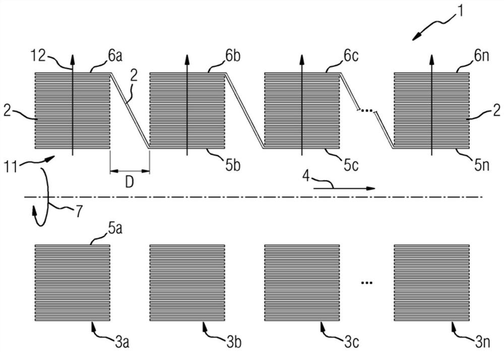
[0030] figure 1 A winding arrangement 1 according to the prior art is shown. The winding arrangement 1 shows a winding of conductors 2 which are electrically insulated from the next coil, for example by inserting an insulating film or by insulating varnish. The conductors 2 are wound such that the turns of the conductors 2 are arranged helically on top of each other in one level. The conductor tracks arranged in a spiral one on top of the other are referred to here as coil layers. Thus, the first coil layer defines the boundaries of the coil interior, which is referred to herein as the segment interior space 11 . Coil layers arranged on top of each other lie on top of each other in one level. In other words, these coil layers constitute disk-shaped disk windings 3a, 3b, 3c . . . 3n as winding segments. The winding segments are arranged one behind the other in the axial direction 4 . In this case, all disk windings 3a, 3b, 3c . . . 3n are arranged relative to one another w...
PUM
Abstract
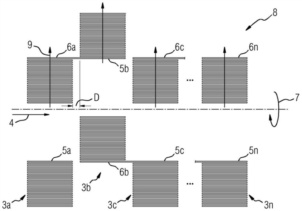
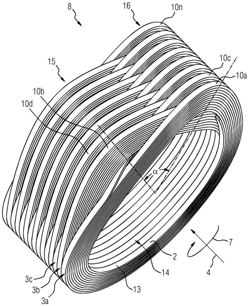
A winding arrangement (8) comprising a plurality of winding segments (3a, 3b, 3c...3n) arranged axially spaced apart from each other and electrically connected in series with each other, the winding segments each having conductors (2) , the conductors are wound from the inner ends (5a, 5b, 5c, 5n) of the respective winding segments (3a, 3b, 3c, . ends (6a, 6b, 6c...6n), and here the winding segments (3a, 3b, 3c...3n) are radially enlarged, wherein at least one winding segment (3a, 3b, 3c...3n) ) on its outer ends (6a, 6b, 6c...6n) electrically with the inner ends (5a, 5b, 5c...5n) of the axially subsequent winding segments (3a, 3b, 3c...3n) connect. In order to be able to manufacture such a winding arrangement inexpensively and to arrange the winding segments of the winding arrangement at a relatively small distance from one another, it is proposed here to design at least one axially subsequent winding segment ( 3a , 3b , 3c . . . 3n ) There are stepped regions (10a, 10b, 10c...10n) in which the inner ends (5a, 5b, 5c...5n) of the subsequent winding segments are arranged radially on the at least one winding At the height of the outer ends (6a, 6b, 6c...6n) of the segments (3a, 3b, 3c...3n), the at least one winding segment is electrically connected to the subsequent winding segment.
Description
technical field [0001] The invention relates to a winding device comprising a plurality of winding segments arranged axially spaced apart from each other and electrically connected in series with each other, the winding segments each having conductors which are wound from the inner ends of the respective winding segments It is wound to the outer end of the individual winding segment, and the winding segment expands in the radial direction, wherein at least one winding segment is electrically connected at its outer end to the inner end of the axially subsequent winding segment. [0002] The invention also relates to a transformer and a coil or choke having such a winding arrangement. Background technique [0003] The aforementioned winding arrangement is known, for example, from document EP 2 251 877 B1. The shown winding arrangement consists of so-called disk windings connected in series, which are arranged at a distance from one another. In this case, the outer end of eac...
Claims
Application Information
Patent Timeline
Application Date:The date an application was filed.
Publication Date:The date a patent or application was officially published.
First Publication Date:The earliest publication date of a patent with the same application number.
Issue Date:Publication date of the patent grant document.
PCT Entry Date:The Entry date of PCT National Phase.
Estimated Expiry Date:The statutory expiry date of a patent right according to the Patent Law, and it is the longest term of protection that the patent right can achieve without the termination of the patent right due to other reasons(Term extension factor has been taken into account ).
Invalid Date:Actual expiry date is based on effective date or publication date of legal transaction data of invalid patent.

