
Rough grinding machine

A coarse grinding and machine body technology, which is applied in the field of mining machinery, can solve the problems of easy damage and maintenance of supporting parts, inconvenience and other problems, and achieve the effects of good bearing capacity, improved stability and improved work efficiency

Active Publication Date: 2018-08-07
CHANGSHA UNIVERSITY
View PDF17 Cites 5 Cited by
  • Summary
  • Abstract
  • Description
  • Claims
  • Application Information

AI Technical Summary

Problems solved by technology

[0004] The main purpose of the present invention is to provide a coarse grinder, aiming to solve the problem that the supporting parts of the existing grinding equipment are easily damaged and inconvenient to maintain

Method used


Image

  • Rough grinding machine
  • Rough grinding machine
  • Rough grinding machine

Examples


Embodiment Construction

[0023] The technical solutions in this embodiment will be clearly and completely described below in conjunction with the accompanying drawings in this embodiment. Obviously, the described embodiments are only part of the embodiments of the present invention, not all of them. Based on the embodiments of the present invention, all other embodiments obtained by persons of ordinary skill in the art without creative efforts fall within the protection scope of the present invention.

[0024] It should be noted that all directional indications (such as up, down, left, right, front, back...) in this embodiment are only used to explain the relative relationship between the various components in a certain posture (as shown in the figure). When the positional relationship, movement conditions, etc., if the specific posture changes, the directional indication will also change accordingly.

[0025] In addition, in the present invention, descriptions such as "first", "second" and so on are ...


PUM


Abstract

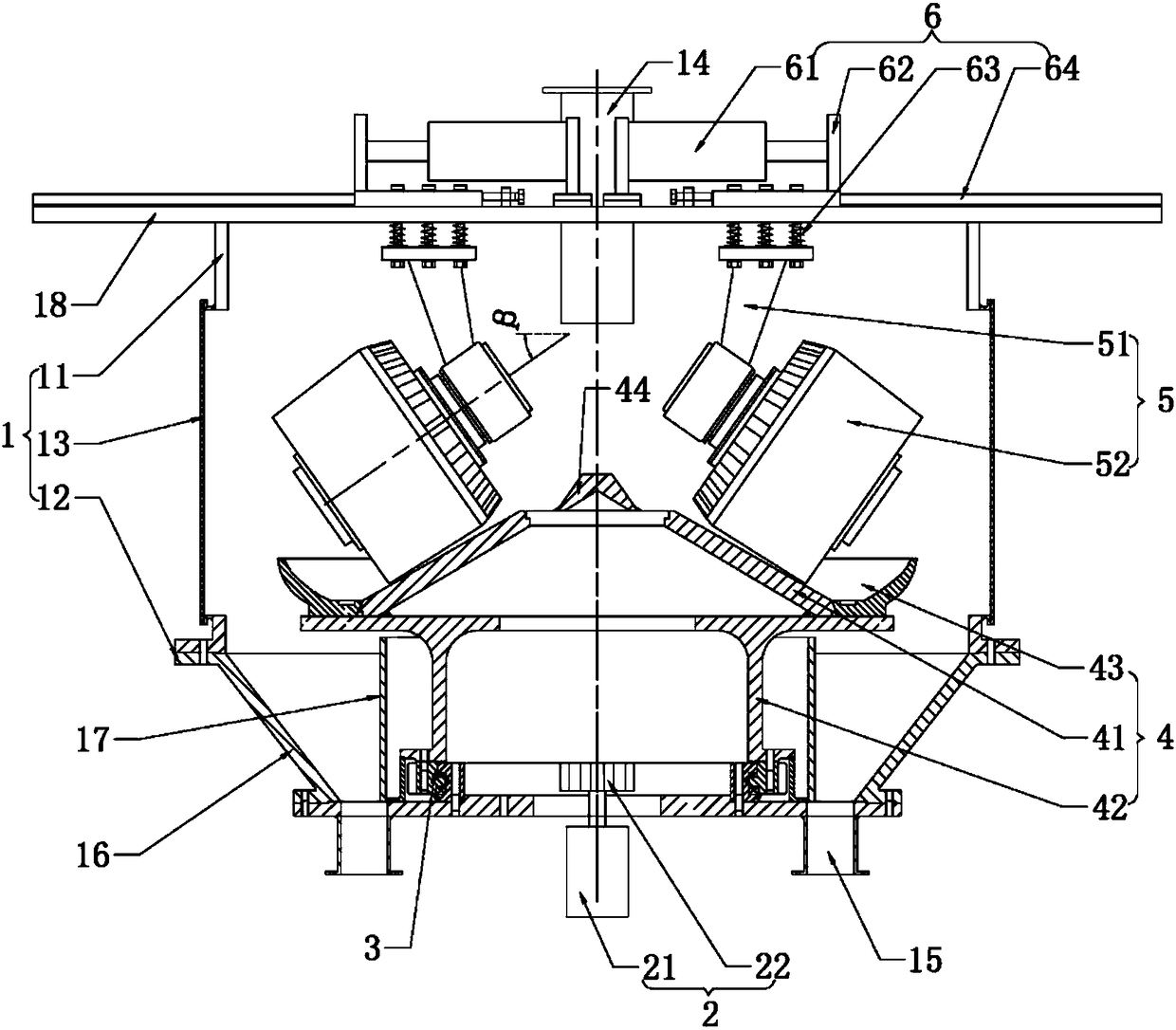
The invention discloses a rough grinding machine. The rough grinding machine comprises a machine body, a driving mechanism as well as a rotational support, a grinding wheel device, a grinding roller device and a loading device which are arranged on the machine body, wherein the rotational support comprises a fixed ring fixedly arranged on the machine body, a revolving ring arranged to be coaxial with the fixed ring and a rolling body arranged between the fixed ring and revolving ring, the driving mechanism is used for driving the grinding wheel device to revolve through the revolving ring, theloading device can be used for driving the grinding roller device to slide on the machine body to realize switchover between a loading state and an overhauling state, in the loading state, the grinding roller device can be pressed on the grinding wheel device through materials, and in the overhauling state, the grinding roller device and the grinding wheel device are kept away from each other. The rough grinding machine has the advantages of simple structure, high rough grinding efficiency and convenient maintenance.

Description

technical field [0001] The invention relates to the field of mining machinery, in particular to a coarse grinder. Background technique [0002] At present, the equipment used for grinding mine materials is mainly various roller mills, while the existing vertical mills are inefficient in the occasions where the finished product particles are relatively coarse. Among them, various roller mills are generally powered by a motor, and the transmission part drives the grinding disc to rotate, and the material is ground through the cooperation of the grinding disc and the grinding roller. The transmission between the transmission part and the grinding disc is generally carried out through the main shaft assembly, and the positioning support is completed by the rolling bearing in the main shaft assembly, and the grinding disc can be rotated under the drive of the motor. However, since the grinding disc and the transmission parts are separately arranged at the two ends of the main sh...

Claims


Application Information

Patent Timeline
Patent Type & Authority Applications(China)
IPC IPC(8): B02C15/14B02C23/00
CPCB02C15/14B02C23/00Y02W30/62
Inventor 陈蕾谈峰庞小兵林涛
Owner CHANGSHA UNIVERSITY
Learn More