An embossing connection cross positioning clamping device and a method for assembling and disassembling test pieces
A clamping device and cross positioning technology, which is applied in the direction of positioning device, storage device, feeding device, etc., can solve the problem that the embossed connection point cannot be accurately centered, so as to improve the operation safety, fast and accurate positioning and clamping, The effect of improving work efficiency
- Summary
- Abstract
- Description
- Claims
- Application Information
AI Technical Summary
Problems solved by technology
Method used
Image
Examples
Embodiment 1
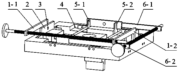
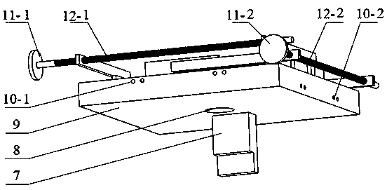
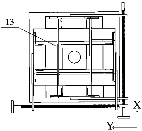
[0034] Embodiment 1: as Figure 1-Figure 11 As shown, a crimping connection cross positioning clamping device, including X-direction connecting plate I1-1, X-direction connecting plate II1-2, baffle plate 2, rectangular groove 4, corner plate I5-1, corner plate II5-2 , Y-direction connecting plate Ⅰ6-1, Y-direction connecting plate Ⅱ6-2, positioning block 7, center hole 8, workbench 9, limit hole Ⅰ10-1, limit hole Ⅱ10-2, rotary handle 11, threaded rod 12 , slide rod 13, threaded hole Ⅰ14-1 and threaded hole Ⅱ14-2;
[0035] The center of the workbench 9 is milled with a through center hole 8. The diameter of the center hole 8 is the same as the outer diameter of the lower mold of the imprinting equipment and the center line coincides. The positioning block 7 is fixed under the workbench 9. Through the positioning block 7 and the center The positioning function of the hole 8 enables the table 9 to be assembled on the lower mold of the imprinting equipment. There are four rectan...
PUM
 Abstract
Description
Claims
Application Information
 - R&D
- Intellectual Property
- Life Sciences
- Materials
- Tech Scout
- Unparalleled Data Quality
- Higher Quality Content
- 60% Fewer Hallucinations
Browse by: Latest US Patents, China's latest patents, Technical Efficacy Thesaurus, Application Domain, Technology Topic, Popular Technical Reports.
© 2025 PatSnap. All rights reserved.Legal|Privacy policy|Modern Slavery Act Transparency Statement|Sitemap|About US| Contact US: help@patsnap.com


