Urban road rainwater utilization technique

A technology for roads and cities, applied in the field of automatic rainwater collection and utilization, can solve the problems of ineffective use of rainwater, easy blockage of collection pipes, complex structure, etc.

Pending Publication Date: 2018-08-07
安吉绿源生态科技有限公司
View PDF9 Cites 1 Cited by
  • Summary
  • Abstract
  • Description
  • Claims
  • Application Information

AI Technical Summary

Problems solved by technology

[0006] This existing technology is to realize the rapid improvement of urban road drainage capacity, but this structure does not effectively use rainwater, it only infiltrates the rainwater when it r...

Method used


Image

  • Urban road rainwater utilization technique
  • Urban road rainwater utilization technique
  • Urban road rainwater utilization technique

Examples


Embodiment 1

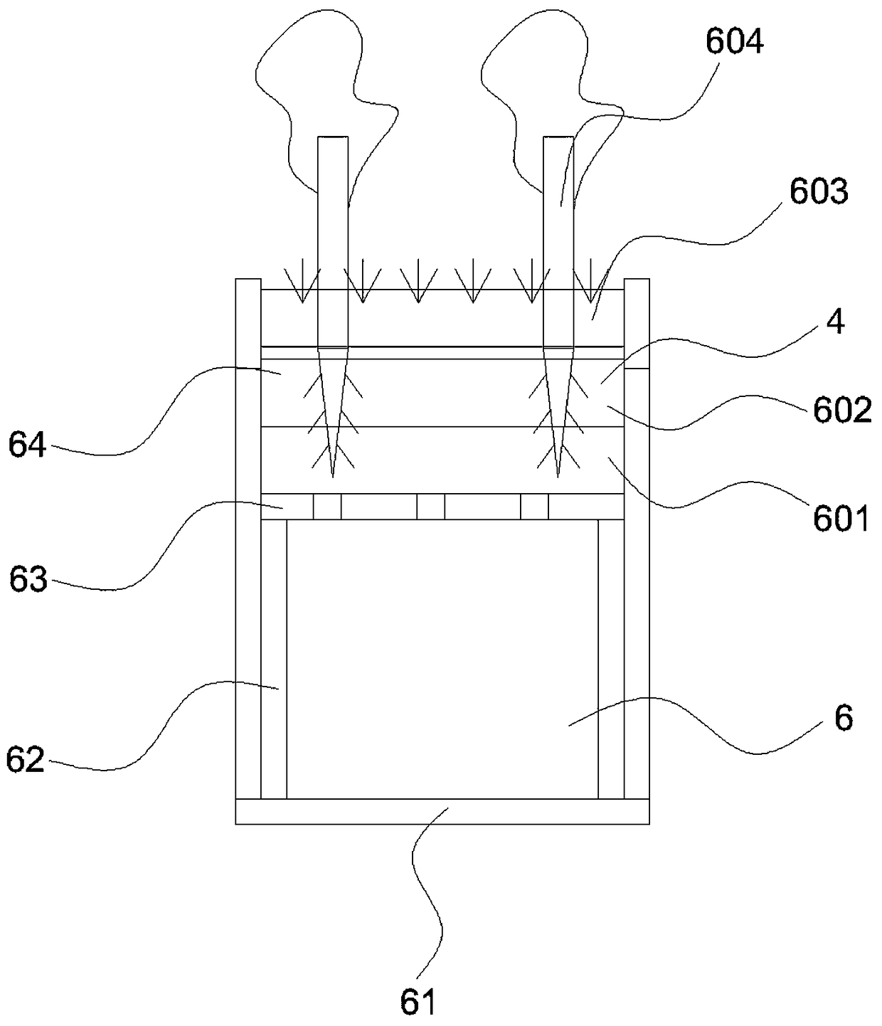
[0039] Embodiment one, such as figure 1 The rainwater utilization technology for urban roads shown includes a motor vehicle lane 1, a non-motor vehicle lane 2 and a sidewalk 3, a green isolation belt 4 is set between the motor vehicle lane 1 and the non-motor vehicle lane 2, and a water storage adjustment chamber is arranged under the green isolation belt 4 6. The water storage adjustment chamber 6 runs through the passage of the city transversely. The water storage adjustment chamber 6 has a bottom flow channel 61, support plates 62 arranged on both sides of the bottom flow channel 61, and partitions with holes supported by the support plates 62 on both sides. plate 63.

[0040]The setting process is firstly to excavate a deep channel deep in the ground, lay stone slabs on the surface of the channel to form the bottom flow channel 61, set support plates 62 on the left and right sides of the stone slabs, and connect the adjacent stone slabs through the front and back of the st...

Embodiment 2

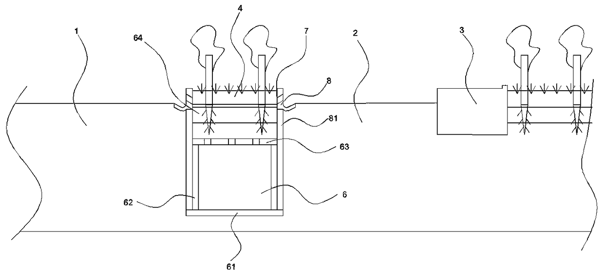
[0044] Embodiment two, such as figure 2 and Figure 4 As shown, because the road surface is relatively large, with the motor vehicle lane 1, the non-motor vehicle lane and the sidewalk 3, only collecting the rainwater in the green isolation belt 4 cannot improve the recovery efficiency. Between the green isolation belt 4 and the motor vehicle lane 1 and between the green isolation belt 4 and the non-motor vehicle lane 2, a rainwater collection channel 7 is arranged to collect the rainwater on the surface of the motor vehicle lane 1, the non-motor vehicle lane 2 and the sidewalk 3 into water storage regulation cavity 6.

[0045] The rainwater collection channel 7 includes a collecting piece 8 . Moreover, the collecting member 8 is arranged on the support plate 81 of the first embodiment, and closely fits with the support plate 81 . The collector 8 has a first side 82 directly connected to the motorway 1 or a non-motorized way 2, and a second side 83 directly connected to th...

Embodiment 3

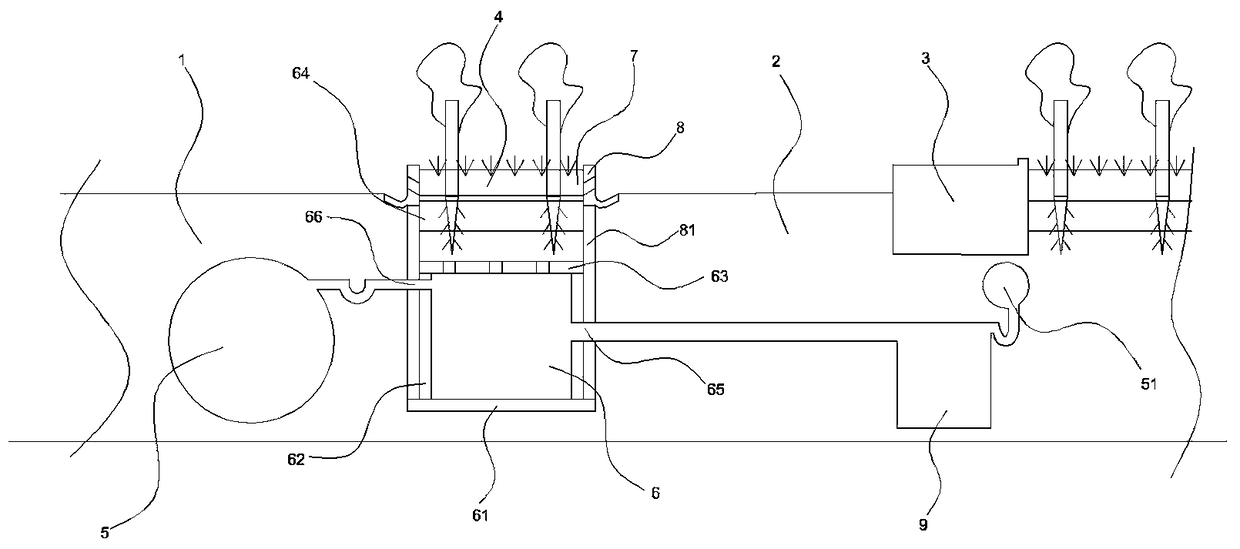
[0048] Embodiment three, such as image 3 and Figure 4 The shown facilitates the flexible and automatic adjustment of the water storage adjustment chamber 6 , a water inlet 65 is provided in the middle of the water storage adjustment chamber 6 , and a water outlet 66 is provided at the upper part of the water storage adjustment chamber 6 . The setting of the water inlet 65 and the water outlet 66 has ensured that the water storage adjustment chamber 6 contains rainwater for a long time.

[0049] There is a rainwater pipe 5 under the motorway 1, and a water supply pipe 51 under the sidewalk 3. A water inlet adjustment chamber 9 is arranged between the water storage adjustment chamber 6 and the water supply pipe 51. The water storage adjustment chamber 6 is connected to the rainwater pipe 5. . When running into a torrential rain, excess rainwater automatically enters the rainwater pipe 5 of the municipal construction when no rainwater is stored in the water storage adjustment...


PUM


Abstract

The invention relates to an automatic rainwater collection and utilization technique, in particular to an urban road rainwater utilization technique, involving a vehicle road, a bicycle lane and a sidewalk. A green isolation belt is arranged between the vehicle road and the bicycle lane; a rainwater pipe is arranged below the vehicle road; a water supply pipe is arranged below the sidewalk. The urban road rainwater utilization technique is characterized in that a storage adjusting chamber is arranged below the green isolation belt; the storage adjusting chamber has a bottom water channel, support plates arranged on two sides of the bottom water channel, and a porous partition plate supported by the support plates on the two sides. It is intended herein that the storage adjusting chamber isarranged below the green isolation belt to allow municipal works to spray less water to green isolating belts in the roads during actual operation, the green isolation belts are kept moist throughoutthe year and are never frozen in winter, and the whole structure is simple.

Description

technical field [0001] The invention relates to the rainwater automatic collection and utilization technology, especially the urban road rainwater utilization technology. Background technique [0002] my country is a country with a shortage of water resources and frequent droughts and floods. For a long time, my country's economic development has been plagued by water shortages. At the same time, a large amount of rainwater resources have been lost in vain. Rainwater is the most direct, fundamental, and economical water resource. The use of rainwater can relieve urban water pressure, improve the urban environment, and reduce municipal sewage pressure, which is conducive to the construction and development of sponge cities. Today, the technology of rainwater utilization is developing rapidly, and the collection and utilization of rainwater on urban roads can effectively relieve the pressure on irrigation water for road green belts. [0003] In the prior art, the public docum...

Claims


Application Information

Patent Timeline
IPC IPC(8): E03F5/04E03F5/10E03F5/14
CPCE03F5/0404E03F5/10E03F5/14
Inventor 梅道亮王慧丽
Owner 安吉绿源生态科技有限公司
Why Eureka
Try Eureka