
Control device and control method

A control device and control method technology, applied in the direction of program control, adaptive control, neural learning method, etc., can solve problems such as inability to perform optimal control

Inactive Publication Date: 2018-08-07
PANASONIC INTELLECTUAL PROPERTY CORP OF AMERICA
View PDF5 Cites 3 Cited by
  • Summary
  • Abstract
  • Description
  • Claims
  • Application Information

AI Technical Summary

Problems solved by technology

[0009] In addition, even if deep neural networks such as convolutional neural networks are used, there is a problem that optimal control cannot be performed.

Method used


Image

  • Control device and control method
  • Control device and control method
  • Control device and control method

Examples


Embodiment approach

[0052] Hereinafter, a control device, a control method, and the like according to the embodiments will be described with reference to the drawings.

[0053] [Configuration of the control device 1]

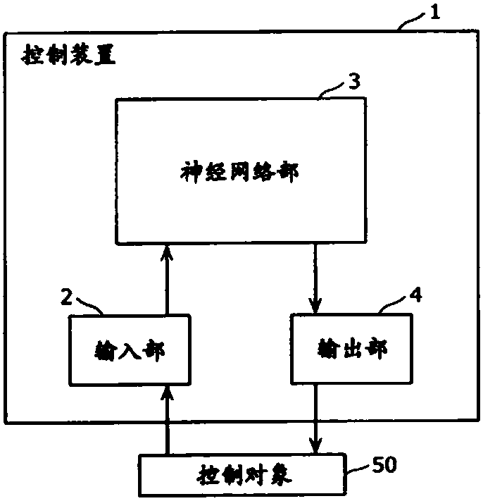
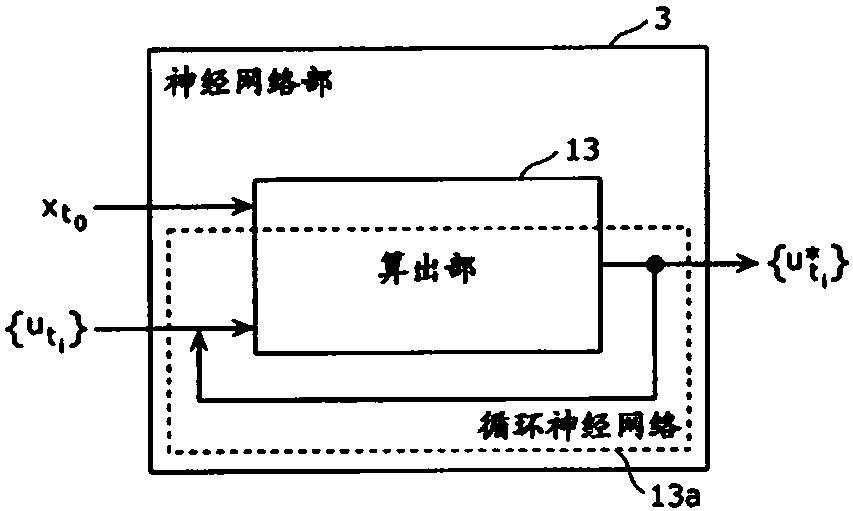
[0054] figure 1 It is a block diagram showing an example of the configuration of the control device 1 of the present embodiment. figure 2 yes means figure 1 A block diagram showing an example of the configuration of the neural network unit 3 is shown.

[0055] The control device 1 is realized by a computer or the like using a neural network, and performs optimal control of the controlled object 50 based on path integrals. For example figure 1 As shown, the control device 1 is composed of an input unit 2 , a neural network unit 3 and an output unit 4 . Here, the control target 50 is, for example, a control target system for which optimal control is performed, such as an autonomously driving vehicle or an autonomously moving robot.

[0056]

[0057] The input unit 2 inputs t...

Deformed example 1

[0136] In the above-described embodiment, the neural network unit 30 has only the calculation unit 13 and has been described as outputting the operation amount sequence calculated by the calculation unit 13 , but the present invention is not limited thereto. The operation amount series calculated by the calculation unit 13 may be averaged and output. Hereinafter, this case will be referred to as Modification 1, and the differences from the embodiment will be mainly described.

[0137] [Neural Network Unit 30]

[0138] Figure 11 It is a block diagram showing an example of the configuration of the neural network unit 30 in Modification 1. right with figure 2 The same elements are attached with the same reference numerals, and detailed explanations are omitted.

[0139] Figure 11 The neural network section 30 shown with respect to figure 2 The shown neural network unit 3 is different in configuration in that it further includes a multiplier 31 , an adder 32 , and a dela...

other Embodiment approach

[0150] (possibility of other implementations)


PUM


Abstract

The invention provides a control device and a control method that can perform optimum control by using a neural network. The control device (1) for performing optimal control by path integral includesa neural network section (3) including a machine-learned dynamics model and cost function, an input section (2) that inputs a current state of a control target (50) and an initial control sequence for the control target into the neural network section, and an output section (4) that outputs a control sequence for controlling the control target, the control sequence being calculated by the neuralnetwork section by path integral from the current state and the initial control sequence by using the dynamics model and the cost function. Here, the neural network section includes a second recurrentneural network incorporating a first recurrent neural network including the dynamics model.

Description

technical field [0001] The present disclosure relates to a control device and a control method, and particularly to a control device and a control method using a neural network. Background technique [0002] As one of optimal controls, path integral control is known (see, for example, Non-Patent Document 1). The optimal control can estimate the future state and reward of the system to be controlled, and grasp it as a structure for finding an optimal sequence of operation quantities. Optimal control can be formulated as a constrained optimization problem. [0003] On the other hand, deep neural networks such as convolutional neural networks have been well-suited for the control of autonomous driving and robotic manipulation. [0004] prior art literature [0005] Non-Patent Document 1: Model Predictive Path Integral Control: From Theory to Parallel Computation https: / / arc.aiaa.org / doi / full / 10.2514 / 1.G001921. [Retrieved on September 29, 2012], Internet <URL:https : / / arc...

Claims


Application Information

Patent Timeline
Patent Type & Authority Applications(China)
IPC IPC(8): G06N3/04G06N3/08G05B13/02
CPCG06N3/049G06N3/084G05B13/027G06N3/044G06N3/045G05B2219/33038G05B2219/34066G05B13/0285G06N7/01
Inventor 冈田雅司
Owner PANASONIC INTELLECTUAL PROPERTY CORP OF AMERICA
Learn More