Automatic directional transmission wireless charging device
A technology of directional transmission and wireless charging, applied in circuit devices, electrical components, etc., can solve the problems of reduced power transmission efficiency, difficulty in aligning the receiving coil with the transmitting coil, and inability to align the transmitting coil with the receiving coil. Use rate, reduce dissipation rate, improve the effect of wireless charging efficiency
- Summary
- Abstract
- Description
- Claims
- Application Information
AI Technical Summary
Problems solved by technology
Method used
Image
Examples
Embodiment 1
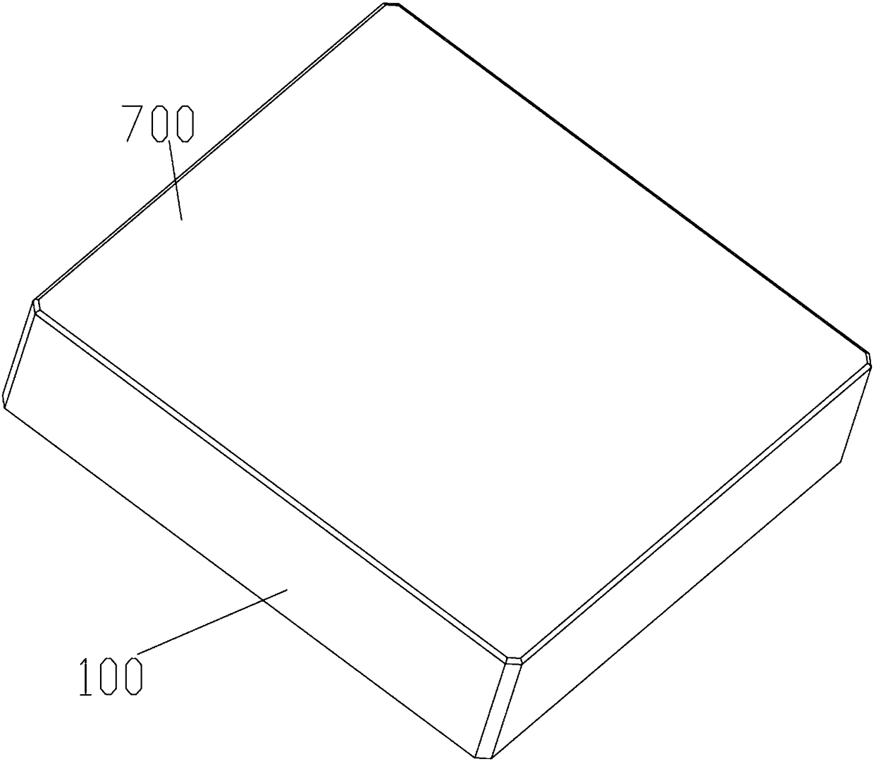
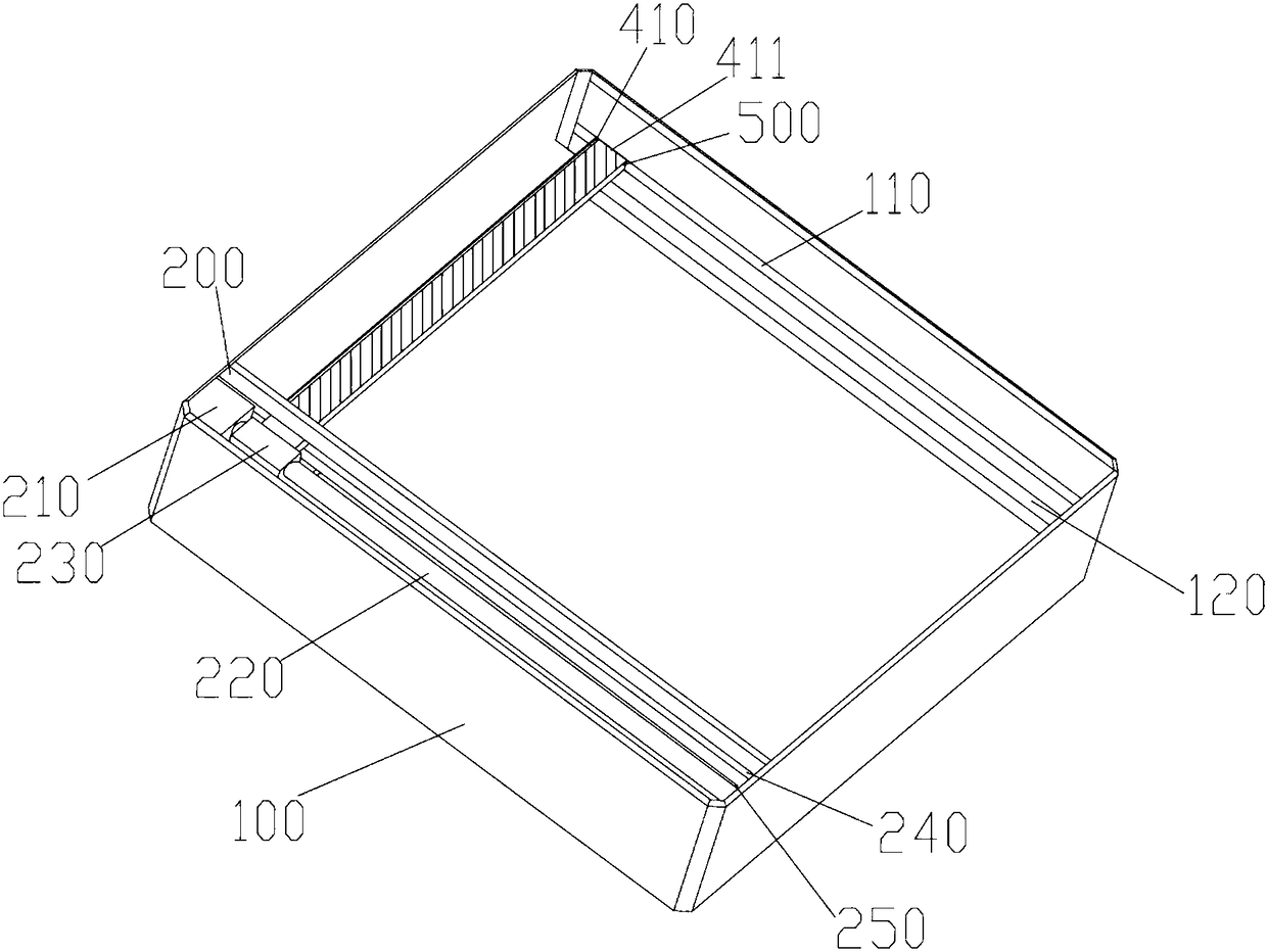
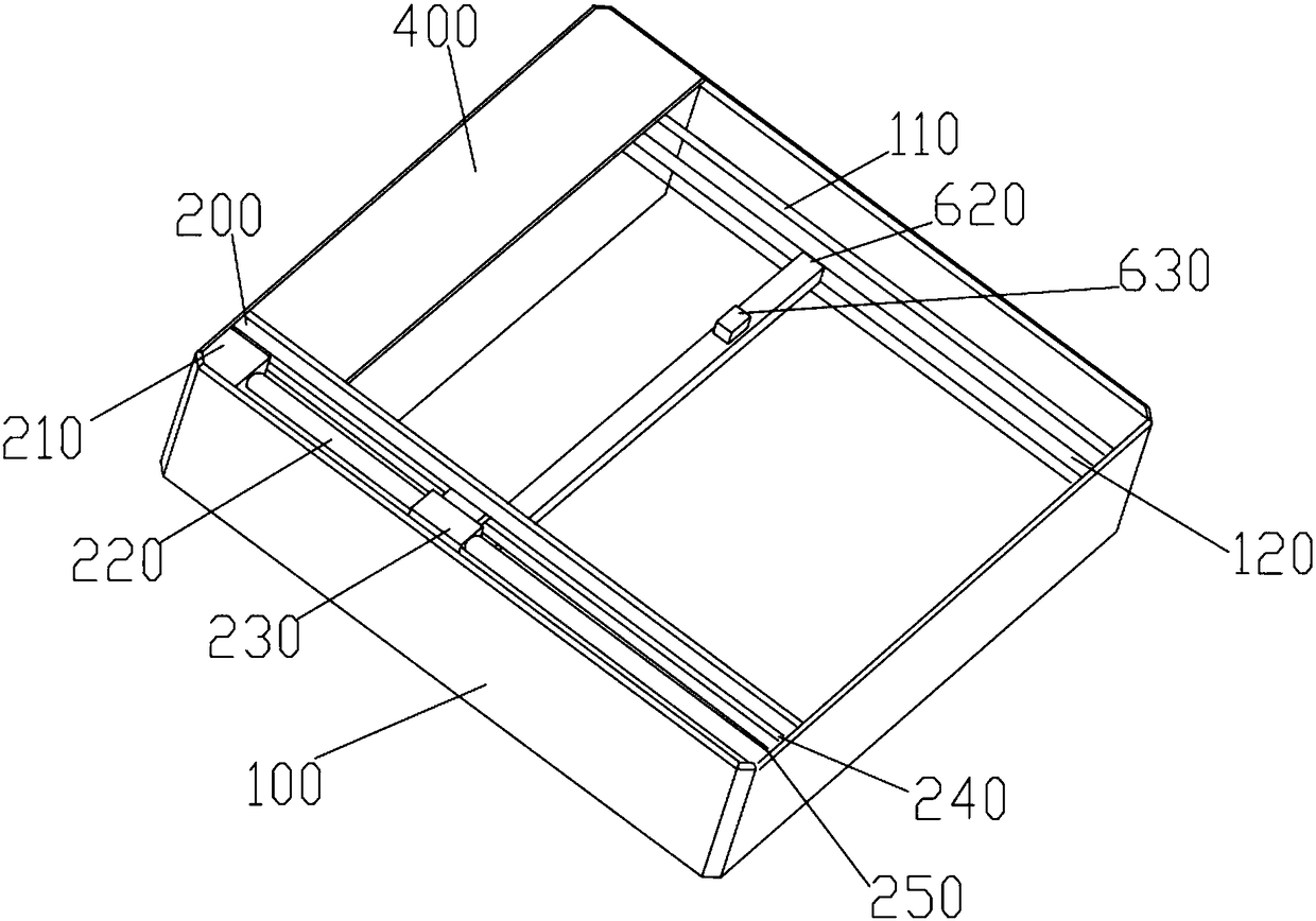
[0041] Such as Figure 1-5 As shown, the present invention provides a wireless charging device for automatic directional transmission, including: a base, a scanning system disposed in the base, a displacement mechanism for moving the transmitting coil, a light-transmitting plate, and a controller.
[0042] The base 100 is a cavity structure, and the base 100 is provided with at least one single-axis moving mechanism for moving the transmitting coil. The transmitting coil is arranged laterally on the moving end of the single-axis moving mechanism, and the transmitting coil can be changed by controlling the single-axis moving mechanism. The transmitting coil is connected to the power supply through a driver, and the driver controls the excitation of the transmitting coil to generate an alternating magnetic field, so that the receiving coil receives and generates electric energy for charging the device to be charged, and the driver is provided with a power A monitoring unit to mo...
Embodiment 2
[0066] The difference from Embodiment 1 is that, if Figure 6-8 As shown, three uniaxial moving mechanisms 620, 640 and 660 with the same structure are provided. The uniaxial moving mechanisms 640 and 660 are arranged on both sides of the uniaxial moving mechanism 620. The base at the second end of the sliding plate in the width direction is provided with In the second accommodation cavity 300, it can be understood that a plurality of single-axis moving mechanisms can be provided as required, and a second positioning cavity is opened at the first end of each single-axis moving mechanism in the length direction.
[0067]A transmitting coil is respectively arranged on the moving end 630 of the single-axis moving mechanism 620 , the moving end 650 of the single-axis moving mechanism 640 and the moving end 670 of the single-axis moving mechanism 660 . At the initial position, the single-axis moving mechanism 660, the single-axis moving mechanism 620 and the sliding plate 500 are a...
Embodiment 3
[0074] The difference from Embodiment 2 is that the transmitting coil includes several groups of concentric coils with different inner diameters, each concentric coil is coaxially arranged, each of the concentric coils is connected to the driver through a controllable switch, and the controllable switch The control terminal is connected to the controller.
[0075] Usually, the specifications of the receiving coils on each device to be charged are not fixed. Several coaxial concentric coils can be set according to the size of several conventional receiving coils. When the transmitting coil and receiving coil are aligned, the same excitation signal Under the premise, each controllable switch is switched one by one, and the receiving coil is excited and charged through different concentric coils. The power monitoring unit monitors the transmission power of each concentric coil in real time, and finally selects the concentric coil with the largest transmission power to excite and c...
PUM
 Abstract
Description
Claims
Application Information
 - R&D
- Intellectual Property
- Life Sciences
- Materials
- Tech Scout
- Unparalleled Data Quality
- Higher Quality Content
- 60% Fewer Hallucinations
Browse by: Latest US Patents, China's latest patents, Technical Efficacy Thesaurus, Application Domain, Technology Topic, Popular Technical Reports.
© 2025 PatSnap. All rights reserved.Legal|Privacy policy|Modern Slavery Act Transparency Statement|Sitemap|About US| Contact US: help@patsnap.com


