Video Processing Method Applied to Embedded System

An embedded system and video processing technology, applied in the field of video processing, can solve problems such as poor ability to read floating-point numbers, no way to interleave, and failure to meet requirements, etc., to speed up the operation speed, improve the operation speed, and solve the problem of sawtooth and horizontal The effect of striae problem

Active Publication Date: 2020-06-12
XIAMEN LENZ COMM
View PDF5 Cites 0 Cited by
  • Summary
  • Abstract
  • Description
  • Claims
  • Application Information

AI Technical Summary

Problems solved by technology

However, the shooting time of each field is different, which means that we will never be able to perfectly interlace
For example, with a digital camera that shoots sixty fields per second, the first field is shot at 1 / 60 of a second, and the second field is shot at 2 / 60 of a second, combining the two fields , if there is no movement of the photographed object, then the combined image looks perfect; but if the photographed object has movement, the content of the two fields will be quite different, then the combined image will produce a A "sawtooth" effect
[0004] The computing power of existing embedded devices to read floating-point numbers is particularly poor. At present, there are many soft algorithms in the existing solutions that can process the image very well, but the computing power of embedded devices is relatively poor, which makes it impossible to realize
The de-interlacing algorithm of the video is far from meeting the requirements, resulting in the defects of jagged or horizontal stripes in the video, resulting in poor visual effect of the video

Method used


Image

  • Video Processing Method Applied to Embedded System

Examples


Embodiment 1

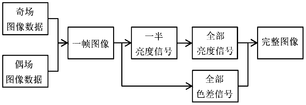
[0018] The invention provides a video processing method applied to an embedded system, the specific principle is as attached figure 1 as shown,

[0019] The method specifically includes the following steps:

[0020] Step S1, alternately scanning progressively to obtain odd field image data and even field image data;

[0021] Step S2, combining the odd-numbered field image data obtained by progressive scanning at the previous moment and the even-numbered field image data obtained by progressive scanning at the current moment to synthesize a frame of image;

[0022] Step S3, obtaining all the luminance signals by synthesizing half of the luminance signals of one frame of images;

[0023] Step S4, combining all the luminance signals and all the color-difference signals of one frame of image to synthesize a complete image.

[0024] In the embodiment of the present invention, preferably, all brightness signals are obtained in step S3, specifically, taking half of the brightness ...

Embodiment 2

[0026] The present invention provides a kind of video processing method that is applied to embedded system, and this method specifically comprises the following steps:

[0027] Step S1, alternately scanning progressively to obtain odd field image data and even field image data;

[0028] Step S2, combining the even-numbered field image data obtained by progressive scanning at the previous moment and the odd-numbered field image data obtained by progressive scanning at the current moment to synthesize a frame of image;

[0029] Step S3, taking half of the luminance signal of a synthesized image and performing quadratic linear interpolation algorithm processing to obtain all luminance signals;

[0030] Step S4, combining all the luminance signals and all the color-difference signals of one frame of image to synthesize a complete image.


PUM


Abstract

The invention discloses a video processing method applied to an embedded system. The method includes the following steps: synthesizing odd field image data and even field image data into one frame ofimage; obtaining all luminance signals through half of the luminance signals for synthesizing one frame of image; and combining all the luminance signals with all color difference signals taken from the synthesized one frame of image into a complete image. According to the method disclosed by the invention, the image can preserve the authenticity of raw data to a maximum extent, and the problem ofsawteeth and horizontal stripes can be effectively solved.

Description

technical field [0001] The invention relates to the field of video processing, in particular to a video processing method applied to an embedded system. Background technique [0002] A dynamic image is composed of a series of continuous static images, each of which is called a frame (frame), and the number of static images contained in a dynamic image per second is called the frame (rate) rate (frameper second, fps). Interlaced scanning is to separate the odd-numbered and even-numbered pixels of a frame image into two fields, and scan the field formed by the odd-numbered lines and the field formed by the even-numbered lines in turn. [0003] Due to the limitations of hardware speed and buffer memory size, general digital cameras cannot continuously shoot progressive images. Therefore, general digital cameras shoot interlaced images. Since interlaced images have half the amount of information than progressive images, therefore This can reduce hardware speed and buffer memor...

Claims


Application Information

Patent Timeline
Patent Type & Authority Patents(China)
IPC IPC(8): H04N7/01
CPCH04N7/012
Inventor 黄艺山王宇朱宏宋利伟
Owner XIAMEN LENZ COMM
Why Eureka
Try Eureka