Cloth perforating device

A technology of punching device and cloth feeding device, which is applied in the cutting of textile materials, textiles and papermaking, metal processing, etc. It can solve the problems of low efficiency, inability to guarantee the distance between holes, time-consuming and labor-intensive problems, and achieve smooth cutting. Effect

Pending Publication Date: 2018-08-10
HANGZHOU WUSHI IND CO LTD
View PDF10 Cites 8 Cited by
  • Summary
  • Abstract
  • Description
  • Claims
  • Application Information

AI Technical Summary

Problems solved by technology

[0002] Fabric production and processing sometimes need to punch holes in the fabric. The existing manual and mechanical punching machines for fabrics can only punch one punching hole at the same time, and cannot punch multiple punching holes on the fabric at the same time.
Sometimes it is necessary to punch multiple holes in the same area of ​​the fabric, so most punching machines function to punch one hole one by one, which is inefficient, time-consuming and laborious, and the distance between holes cannot be guaranteed. Therefore, a new method is proposed. Cloth punching device

Method used


Image

  • Cloth perforating device
  • Cloth perforating device
  • Cloth perforating device

Examples


Embodiment Construction

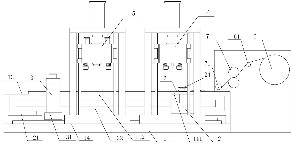
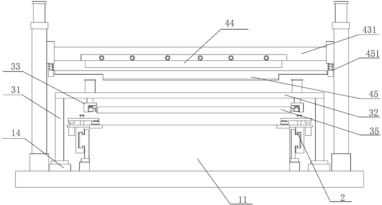
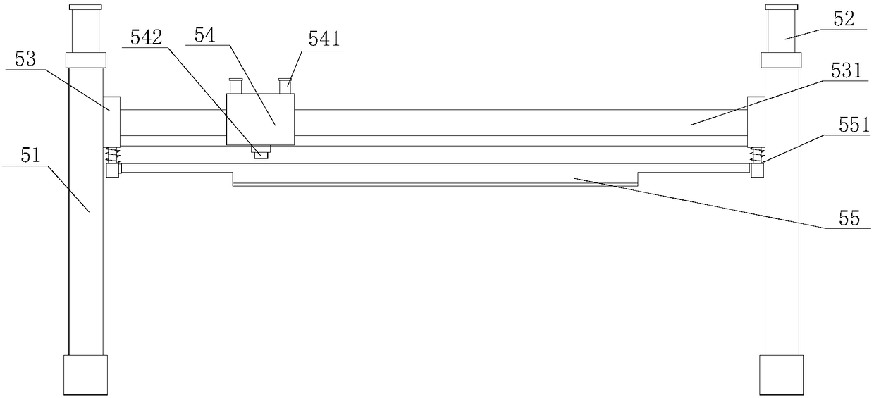
[0019] refer to Figure 1 to Figure 6 A cloth punching device of the present invention comprises a frame 1, a positioning cloth feeding device 2, a smoothing device 3, a cloth cutting device 4, a punching device 5, an unwinding device 6 and a conveying roller mechanism 7, and the frame 1 A workbench 11 is provided, and the bottom of the positioning and feeding device 2 is provided with a lifting platform 21, and the lifting platform 21 is symmetrically distributed on both sides of the working platform 11, and the first sliding seat 23 is provided on the described lifting platform 21, The first sliding seat 23 is provided with a positioning mechanism 24, the two sides of the workbench 11 are symmetrically provided with second guide rails 14, and the two sides of the smoothing device 3 are symmetrically provided with first walking frames 31. The first traveling frame 31 is movably installed on the second guide rail 14, the first traveling frame 31 is provided with a smoothing ro...


PUM


Abstract

The invention provides a cloth perforating device. The cloth perforating device comprises a rack, a positioning and cloth conveying device, a flattening device, a cloth cutting device, a perforating device body, an unwinding device and a conveying roller mechanism. A workbench is arranged on the rack. A lifting platform is arranged at the bottom of the positioning and cloth conveying device. A flattening roller is arranged on the flattening device. A cutting knife assembly is arranged on the cloth cutting device. A second lifting frame and a punching trolley are arranged on the perforating device body. A third guide rail is arranged on the second lifting frame. The punching trolley is driven by a motor to move in the horizontal direction of the third guide rail. A punching cylinder is arranged on the punching trolley and matched with a punching head. A tensioning roller is arranged between the unwinding device and the conveying roller mechanism. The end of a piece of cloth is conveyedforwards through the positioning and cloth conveying device. The cut cloth is flattened through the flattening device. The flattened cloth is perforated through the punching trolley capable of movingtransversely after being primarily positioned.

Description

【Technical field】 [0001] The invention relates to the technical field of cloth production, in particular to a cloth punching device. 【Background technique】 [0002] Cloth production and processing sometimes need to be punched on the cloth, and the existing cloth can only punch one punching hole at the same time basically with manual and mechanical punching machines, and cannot punch multiple punching holes on the textile at the same time. Sometimes it is necessary to punch multiple holes in the same area of ​​the fabric, so most punching machines function to punch one hole one by one, which is inefficient, time-consuming and laborious, and the distance between holes cannot be guaranteed. Therefore, a new method is proposed. Cloth punching device. 【Content of invention】 [0003] The purpose of the present invention is to solve the problems in the prior art, and propose a cloth punching device, through which the end of the cloth is conveyed forward by the positioning cloth ...

Claims


Application Information

Patent Timeline
Patent Type & Authority Applications(China)
IPC IPC(8): B26F1/14B26D1/08B26D7/01B26D7/08D06H7/00
CPCD06H7/00B26D1/085B26D7/015B26D7/018B26D7/08B26F1/14
Inventor 吴逢强
Owner HANGZHOU WUSHI IND CO LTD
Why Eureka
Try Eureka