
Teleporter

A transmission device and main support rod technology, applied in the field of transportation, can solve the problems of uneven force on the substrate, changes in the use process, and increase the risk of damage to the back of the substrate, so as to reduce the amount of bending deformation, avoid impacting fragments, and reduce damage to the back Probability Effects on Risk

Active Publication Date: 2020-02-07
WUHAN CHINA STAR OPTOELECTRONICS TECH CO LTD
View PDF5 Cites 0 Cited by
  • Summary
  • Abstract
  • Description
  • Claims
  • Application Information

AI Technical Summary

Problems solved by technology

[0003] The purpose of the present invention is to provide a conveying device to solve the problem of uneven local force on the substrate due to differences in installation and manufacturing of independent free rollers or changes in the use process, which will increase the risk of damage to the back of the substrate. technical issues of probability

Method used


Image

  • Teleporter
  • Teleporter
  • Teleporter

Examples


Embodiment Construction

[0020] The following will clearly and completely describe the technical solutions in the embodiments of the present invention with reference to the accompanying drawings in the embodiments of the present invention. Obviously, the described embodiments are only some, not all, embodiments of the present invention. Based on the embodiments of the present invention, all other embodiments obtained by persons of ordinary skill in the art without creative efforts fall within the protection scope of the present invention.

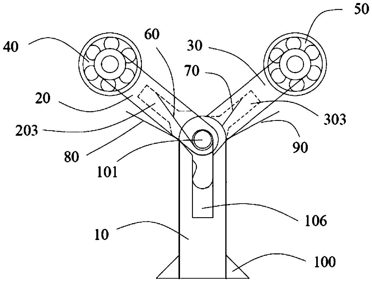
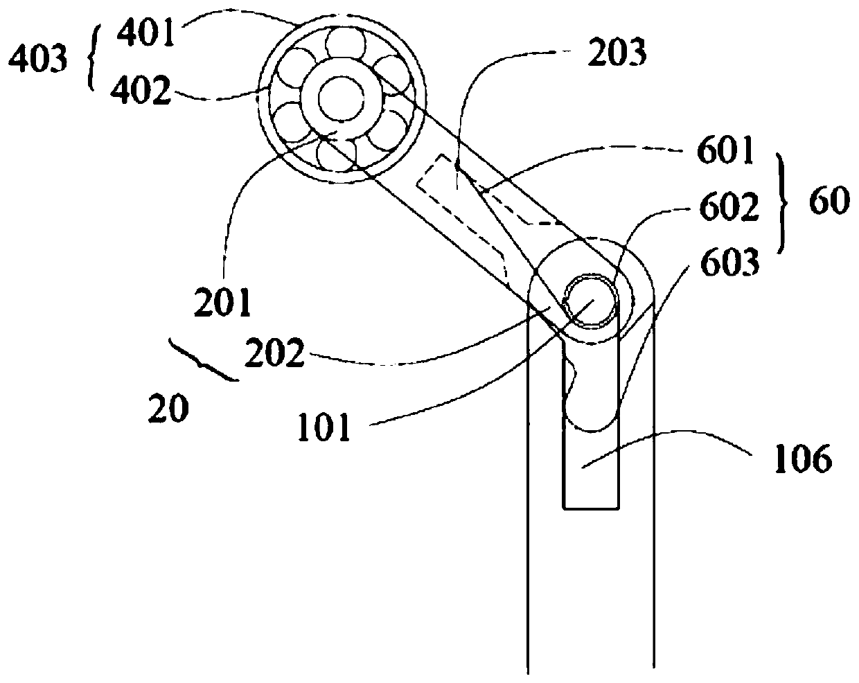
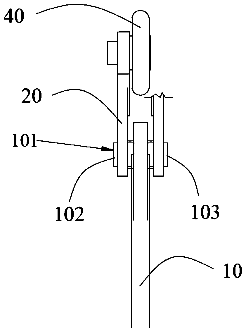
[0021] see figure 1 , the present invention provides a conveying device for conveying substrates, including a main pole 10, a first branch pole 20, a second branch pole 30, and a first elastic support member 60 and a second pole provided on the main pole 10. Two elastic supports 70, the first branch rod 20 and the second branch rod 30 are rotatably connected to the opposite sides of the main rod 10 and arranged in a staggered manner, the first branch rod 20 and the...


PUM


Abstract

The invention provides a conveying device. The conveying device is used for conveying a bade plate, and comprises a main support rod, two branch support rods and two elastic support elements arrangedon the main support rod, wherein the two branch support rods are rotationally connected to the two opposite sides of the main support rod separately, and oppositely arranged in a staggered manner; thetwo branch support rods are capable of stretching relative to the main support rod; the two elastic support elements are used for elastically supporting the two branch support rods when the two branch support rods relatively stretch; a free roll is fixedly connected to one end away from the main support rod, of each branch support rod; and the two branch support rods support the base plate when the two free rolls convey the base plate. According to the conveying device provided by the invention, the technical problem that the local stress of the base plate is non-uniform because unevenness iseasily generated between the independent free rolls due to the installation and production difference or the use process change of the free rolls, and then the damage risk probability of the back surface of the base plate is increased, is solved.

Description

technical field [0001] The invention relates to the field of conveying technology, in particular to a substrate conveying device. Background technique [0002] Liquid crystal display industry process equipment often uses free roller structure, and free roller is also used in the conveying structure of various equipment. The function of the free roller is to undertake and transfer the glass substrate, and provide transportation guarantee for the gap where the power conveying substrate cannot be set. For example, if the transmission roller between two devices is disconnected, a free roller must be installed to ensure the substrate transportation and avoid substrate bending deformation. Excessively large is bad. However, the current independent design of free rollers, due to differences in installation and manufacturing or changes in the use process, unevenness is likely to occur between free rollers, resulting in uneven local stress on the substrate, which in turn increases t...

Claims


Application Information

Patent Timeline
Patent Type & Authority Patents(China)
IPC IPC(8): B65G49/06B65G39/12
CPCB65G39/12B65G49/06
Inventor 刘学敏
Owner WUHAN CHINA STAR OPTOELECTRONICS TECH CO LTD
Learn More