Novel profile cutting device for tempered film

A tempered film and shape technology, applied in glass cutting devices, glass manufacturing equipment, manufacturing tools, etc., can solve problems such as low efficiency, complex structure, cumbersome process, etc., and achieve high efficiency, high safety, and close contact and transmission relationship Effect

Inactive Publication Date: 2018-08-10
CHENGDU JUNSHUO RUIZHI INFORMATION TECH CO LTD
View PDF1 Cites 2 Cited by
  • Summary
  • Abstract
  • Description
  • Claims
  • Application Information

AI Technical Summary

Problems solved by technology

[0005] The purpose of the present invention is to solve the problems of complex structure, cumbersome process and low efficiency of the tempered film cutting device in the prior art, and provide a new type of tempered film cutting device with simple structure, convenient operation and higher efficiency

Method used


Image

  • Novel profile cutting device for tempered film
  • Novel profile cutting device for tempered film
  • Novel profile cutting device for tempered film

Examples


Embodiment 1

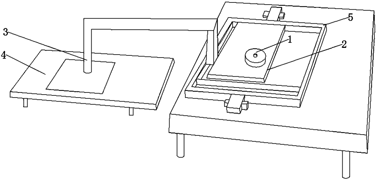
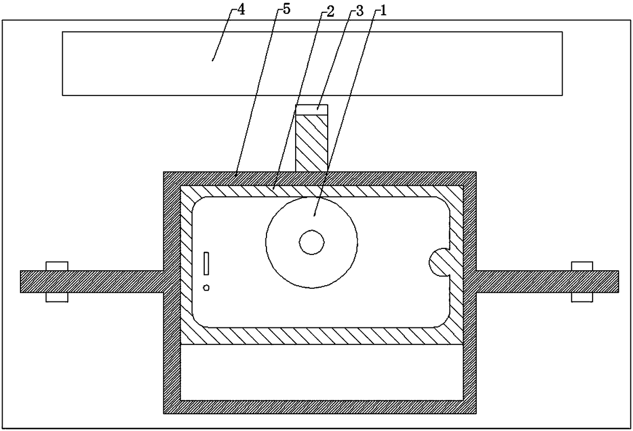
[0030] A new type of tempered film shape cutting device, including a workbench, one side of the workbench is provided with a tempered film fixing table, when the tempered film needs to be cut, the tempered film is placed on the tempered film fixing table; working There is a sliding block on the table, and a cavity is opened inside the sliding block. The shape of the inner wall of the cavity is adapted to the shape of the required toughened film. The inner wall of the cavity is also contacted with a driving wheel, which can drive The sliding block as a whole moves along a certain track; the side of the sliding block close to the tempered film fixing table is connected with a cutting knife through a connecting rod, and the cutting knife can move along the same track as the sliding block to cut the tempered film.

[0031] During the working process, the driving wheel is started, and the driving wheel drives the sliding block and the cutting knife to move along a certain track to c...

Embodiment 2

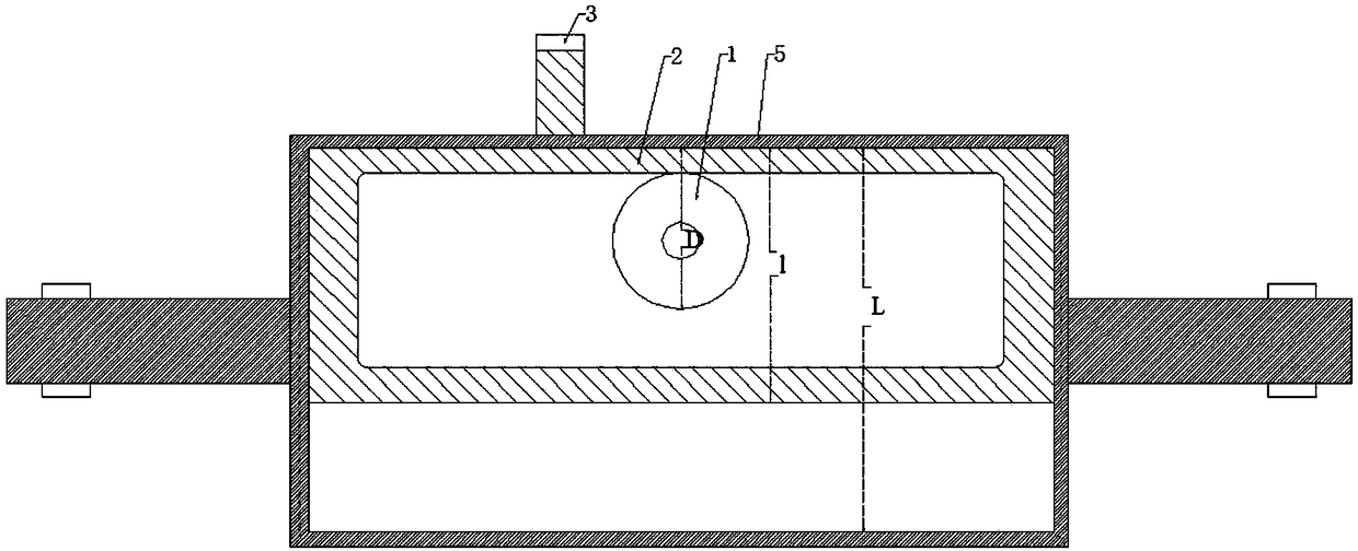
[0033] On the basis of Example 1, the workbench is provided with an outer frame that can move along the length direction of the tempered film fixed table, the sliding block is sleeved in the inner cavity of the outer frame, and the outer frame is fixed in the length direction of the outer frame by two block fixed. Such setting can make the contact and transmission relationship between the sliding block and the driving wheel closer, and enhance the stability and working efficiency of the whole device during operation.

Embodiment 3

[0035] On the basis of Example 2, the width L of the inner cavity of the outer frame is greater than the sum of the width l of the outside of the sliding block and the outer diameter D of the driving wheel, that is, L≥l+D, so that the outer frame will not go to the tempered film The direction of the fixed table is close, which makes the overall safety higher.


PUM


Abstract

The invention discloses a novel profile cutting device for a tempered film, which belongs to the technical field of tempered film technology, and aims to solve the problems of complex structure, fussyflow and low efficiency of the tempered film cutting device in the prior art and provide a novel profile cutting device for a tempered film with simple structure, convenient operation and higher efficiency. The novel profile cutting device for a tempered film comprises a workbench. One side of the workbench is provided with a tempered film fixing platform. A sliding block is arranged on the workbench. A cavity is arranged in the sliding block. The shape of the inner wall of the cavity is matched with the shape of the required tempered film. The inner wall of the cavity is also provided with adriving wheel in contact mode. One side of the sliding block, near the tempered film fixing platform, is connected with a cutting knife through a connecting rod. The novel profile cutting device fora tempered film has the advantages of simple structure, stability, accuracy and high efficiency and can be applied to the cutting of the tempered film with various required shapes by changing the shape of the inner wall of the cavity of the sliding block. It is suitable for promotion.

Description

technical field [0001] The invention belongs to the technical field of tempered film, and in particular relates to a novel shape cutting device for tempered film. Background technique [0002] With the development of science and technology and the progress of society, mobile phones have become an indispensable and highly popular electronic device in people's lives, and the tempered film on the screen of the mobile phone is to prevent the mobile phone from falling when it falls The screen shattered. The tempered film has good prestress, can resist wind pressure, cold and heat, and impact, and provides a higher level of protection for the mobile phone screen. However, in the process of preparing the tempered film at present, the cutting is inconvenient and the accuracy is low, and the process cost is relatively high. [0003] The invention patent with the application number CN201720894448.1 discloses a tempered film cutting device, including a workbench, first slide rails ar...

Claims


Application Information

Patent Timeline
Patent Type & Authority Applications(China)
IPC IPC(8): C03B33/03
Inventor 张德彬
Owner CHENGDU JUNSHUO RUIZHI INFORMATION TECH CO LTD
Why Eureka
Try Eureka