Tensile limiting isolation bearing

A seismic isolation bearing and tensile technology, which is applied in the direction of earthquake prevention, bridge parts, bridge construction, etc., can solve the problem of increasing the vertical height or horizontal dimension of the bearing, affecting the horizontal mechanical properties of the bearing body, and seismic isolation rubber bearing In order to avoid problems such as failure and damage, the effect of enhancing tensile bearing capacity, improving stability and safety, and avoiding tensile damage

Active Publication Date: 2018-08-10
BEIJING UNIV OF CIVIL ENG & ARCHITECTURE
View PDF11 Cites 10 Cited by
  • Summary
  • Abstract
  • Description
  • Claims
  • Application Information

AI Technical Summary

Problems solved by technology

However, these structures also have problems that the tensile structure significantly affects the horizontal mechanical properties of the bearing body, and the vertical height or horizontal dimension of the bearing increases significantly, which deserves further research and improvement.
Although the use of ordinary vibration-isolation rubber bearings can satisfy the function of horizontal vibration isolation, if excessive horizontal shear deformation or excessive rotation angle occurs to the vibration-isolation rubber bearings, the vibration-isolation rubber bearings will fail and even cause isolation. Earthquake structure topples and collapses

Method used


Image

  • Tensile limiting isolation bearing
  • Tensile limiting isolation bearing
  • Tensile limiting isolation bearing

Examples


Embodiment Construction

[0026] In order to make the purpose, technical solutions and advantages of the embodiments of the present invention clearer, the technical solutions in the embodiments of the present invention will be clearly described below in conjunction with the accompanying drawings in the embodiments of the present invention. Obviously, the described embodiments are the Invent a modular embodiment, not an entire embodiment. Based on the embodiments of the present invention, all other embodiments obtained by persons of ordinary skill in the art without making creative efforts belong to the protection scope of the present invention.

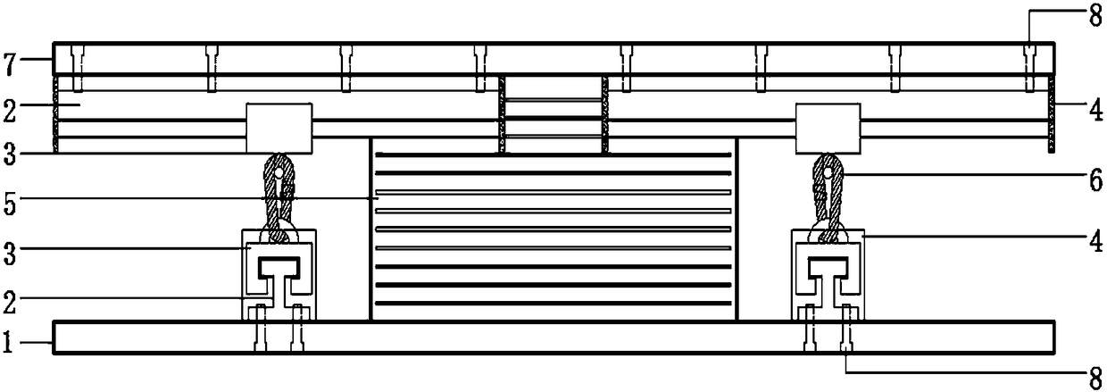
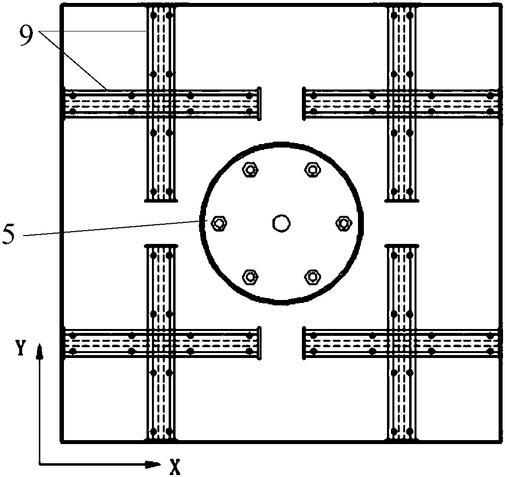
[0027] figure 1 It is a front view of the tension-limiting shock-isolation bearing provided according to the embodiment of the present invention, figure 2 It is a schematic diagram of the positional relationship between the support body 5 and the tension limiting device provided according to the embodiment of the present invention; figure 1 and figure 2 A...


PUM


Abstract

The invention provides a tensile limiting isolation bearing. The tensile limiting isolation bearing comprises a bearing body, an upper connecting plate, a lower connecting plate and a tensile limitingdevice, wherein the upper connecting plate and the lower connecting plate are fixed with the upper and lower ends of the bearing body; the tensile limiting device is arranged on the periphery of thebearing body; the tensile limiting device comprises two slip limiting mechanisms which are orthogonal to each other; the two slip limiting mechanisms are connected through a flexible material. The tensile limiting device is arranged on the periphery of the bearing body, and slips freely along an axis X and an axis Y, so that the maximum deformation of the bearing body along the axis X and the axisY is limited without affecting the horizontal isolation performance of the bearing body. The flexible material bears the tensile force on the bearing body along an axis Z, so that the Z-axis tensilerigidity of the bearing is effectively enhanced. In the case of strong shock, the tensile limiting device can effectively avoid instability when the deformation of the bearing body exceeds a deformation limit; meanwhile, the Z-axis tensile performance of the bearing is enhanced, and the stability and safety of the isolation bearing are improved.

Description

technical field [0001] The invention relates to the technical field of shock isolation, and more specifically, to a tension-limiting shock-isolation support. Background technique [0002] With the rapid advancement of social modernization and urbanization, the population gradually tends to concentrate, and the social wealth grows rapidly. The huge energy carried by earthquakes also poses an increasing threat to human civilization. This forces engineering anti-seismic personnel to continuously explore and update the theory of structural anti-seismic design and methods of disaster prevention and mitigation. [0003] Earthquake disasters are mainly caused by the forced vibration of structures caused by ground motion. The basic principle of seismic isolation is to reduce the horizontal stiffness of the structure, prolong the natural vibration period of the structure, and increase the structural damping by setting the seismic isolation device, thereby effectively reducing the se...

Claims


Application Information

Patent Timeline
Patent Type & Authority Applications(China)
IPC IPC(8): E04B1/98E04H9/02E01D19/00E01D19/04
CPCE01D19/00E01D19/04E04H9/021
Inventor 吴宜峰李爱群张瑞君
Owner BEIJING UNIV OF CIVIL ENG & ARCHITECTURE
Why Eureka
Try Eureka