Non-anchor-rod type multifunctional embedded box iron and anchoring and installing method

An installation method and pre-embedded groove technology, which are applied in the direction of construction and building structure, can solve the problems of inconsistent deformation, instability, uneven stress and deformation of the groove opening, and achieve the purpose of increasing the longitudinal shear bearing capacity, The tensile bearing capacity is improved, and the effect of installation and application is enhanced

Active Publication Date: 2019-03-29
WUHAN RES INST OF MATERIALS PROTECTION
View PDF9 Cites 2 Cited by
  • Summary
  • Abstract
  • Description
  • Claims
  • Application Information

AI Technical Summary

Problems solved by technology

Due to the structural reasons of the traditional embedded channel, the tensile performance of the notch of the channel near the anchor is better than that of the notch far away from the anchor. In order to meet the design requirements, it is necessary to adjust the anchor The number of anchor rods is used to make the performance of each stressed point of the channel meet the design requirements. Even so, the stress of each point on the channel is still different. When the force is applied, the deformation of the channel opening is inconsistent. It is difficult to meet the installation requirements of consistent slot deformation. Therefore, the traditional embedded channel technology solution has the problem of uneven force and deformation at each point on the channel, and there is a risk of instability.
[0004] The traditional pre-buried channel mainly bears force through the notch, and the material used in the channel is generally Q345B. This structure and material properties itself determine that the tensile and fatigue properties of the pre-buried channel are difficult to achieve. high level
[0005] For traditional pre-embedded channel anchor bolt fixing, no matter using lower-cost riveting technology or more stable welding technology, the anchor bolt fixing cost is always an important cost of the pre-embedded channel except for the channel, accounting for the About 30% of the processing cost, coupled with the high-cost hot-rolled technology used in the pre-embedded channels for rail transit, leads to the high overall cost of the pre-embedded channels. main reason to use

Method used


Image

  • Non-anchor-rod type multifunctional embedded box iron and anchoring and installing method
  • Non-anchor-rod type multifunctional embedded box iron and anchoring and installing method
  • Non-anchor-rod type multifunctional embedded box iron and anchoring and installing method

Examples


Embodiment 1

[0041] Example 1 (When the design tensile and shear load bearing capacity is small)

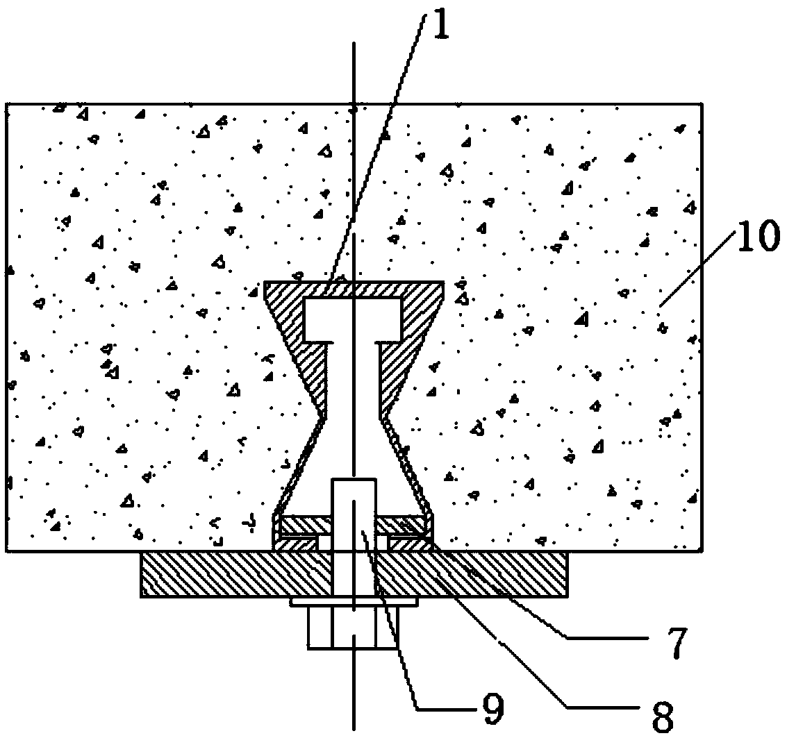
[0042] The installation diagram of the anchor installation method of this embodiment is shown in figure 1 , The anchoring device used in the anchoring installation method includes embedded channel steel 1, single-head bolt 9, installation assembly 8 and toothed wing nut 7, such as Picture 10 As shown, the pre-buried channel steel 1 includes a trough body and a main chute 101 provided on the trough body. Both sides of the trough body are provided with a waist structure. The pre-buried channel steel 1 passes through the waist structure and the concrete 10 The main chute 101 is recessed in the notch, and the force-bearing portion 104 is formed at the notches on both sides of the main chute 101. The inner side of the force-bearing portion 104 is provided with anti-slip teeth 105, The top of the main chute 101 is provided with a T-shaped chute 2, and the T-shaped chute 2 is integrated with the groove...

Embodiment 2

[0044] Example 2 (When the design tensile bearing capacity is large, there is no requirement for the shear bearing capacity)

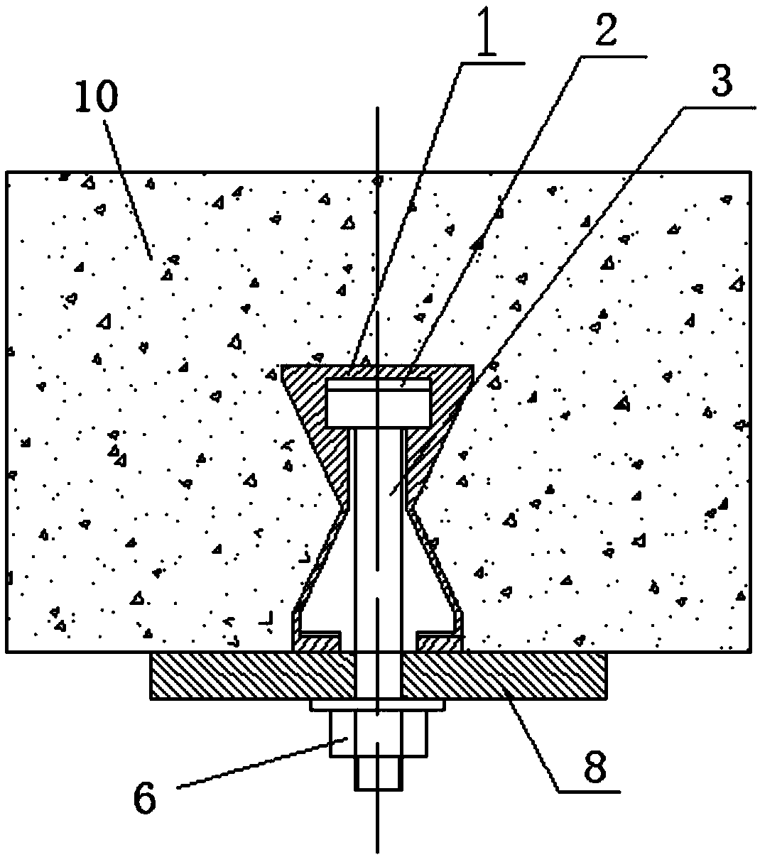
[0045] The installation diagram of the anchor installation method of this embodiment is shown in figure 2 The anchoring device used in the anchoring installation method includes embedded channel steel 1, T-bolt 3, mounting assembly 8 and fastening nut 6. The embedded channel steel 1 in this embodiment is the same as that in embodiment 1, using T-shaped chute 2. Integrated with the tank body.

[0046] The embedded channel steel 1 is embedded and anchored and installed in the concrete 10. When fixing the installation component 8, first install the T-bolt 3 in the T-shaped chute 2, move it to the position to be installed, and then install the component 8 is sleeved on the threaded end of the T-bolt 3, and a nut 6 is tightened on the threaded end of the T-bolt 3, and the mounting assembly 8 is fixed by the tightening nut 6.

Embodiment 3

[0047] Example 3 (when the design tensile and shear bearing capacity are large)

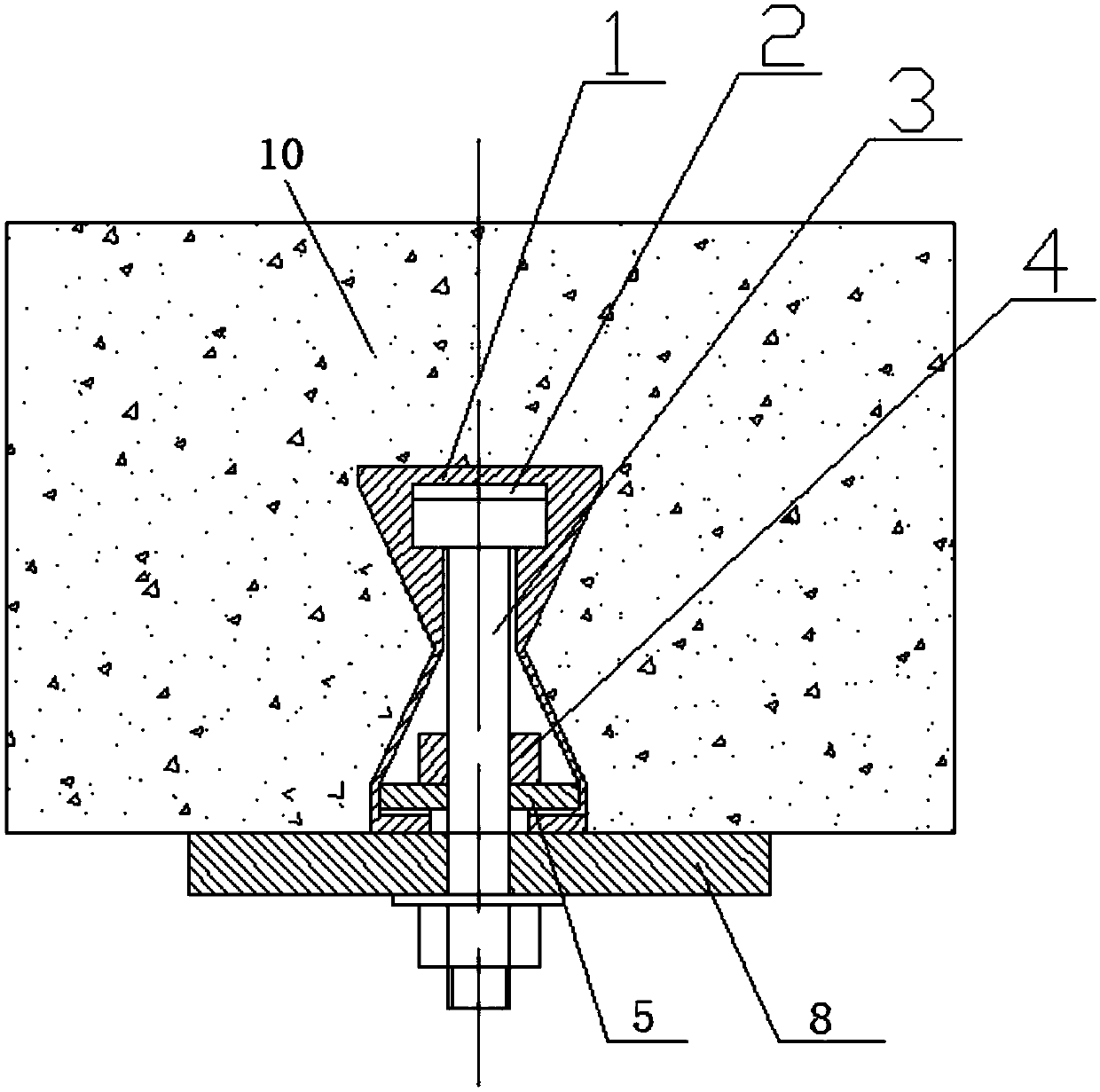
[0048] The installation diagram of the anchoring installation method of this embodiment is shown in image 3 The anchoring device used in the anchoring installation method includes embedded channel steel 1, T-bolt 3, mounting assembly 8, fastening nut 6, fixing nut 4, and toothed butterfly pad 5. In this embodiment, the embedded channel steel 1 and As in Embodiment 1, the T-shaped chute 2 is integrated with the groove body.

[0049] The embedded channel steel 1 is embedded and anchored and installed in the concrete 10. When fixing the installation assembly 8, before the T-bolt 3 is installed in the T-shaped chute 2, the fixing nut 4 and the fixing nut 4 and Toothed butterfly block 5, then install the T-bolt 3 in the T-shaped chute 2, move to the position where it needs to be installed, and then tighten the fixing nut 4 to press the toothed butterfly block 5 on the bearing part 104 To fix the T-bolt 3...


PUM


Abstract

The invention discloses non-anchor-rod type multifunctional embedded box iron and an anchoring and installing method. The embedded box iron comprises a groove body and a main slide groove arranged onthe groove body. The embedded box iron is embedded and anchored in concrete through waist narrowing structures on the two sides of the groove body. A groove opening of the main slide groove is narrowed on the two sides, and a narrowed force bearing pat is formed at the groove opening. Antiskid teeth are arranged on the inner side of the force bearing part. A T-shaped slide groove is formed in theinner top of the main slide groove and can be split. An auxiliary slide groove with a conical section is formed in the inner top of the main slide groove, an auxiliary slider matched with the auxiliary slide groove in section shape is arranged in the auxiliary slide groove. A T-shaped slide groove is formed in the side, close to the groove opening of the main slide groove, of the auxiliary slider.A T-shaped bolt, a fastening nut, a fixing nut, a single-end bolt, a toothed butterfly-shaped gasket and a toothed butterfly-shaped nut are selected to be fixedly installed according to different load requirements of installation assemblies. The embedded box iron is low in installation cost, the tensile performance, longitudinal shearing performance and fatigue performance are greatly improved, the overall channel anchoring force is consistent, and the overall channel stability is improved.

Description

Technical field [0001] The invention belongs to the field of engineering construction, and relates to a pre-buried channel installation technology, in particular to a non-anchor-type multifunctional pre-buried channel steel and an anchoring installation method. Background technique [0002] The embedded chute technology refers to the pre-embedding of C-shaped channel steel with anchor rods in the concrete during the concrete pouring process, and the later mechanical and electrical installation to fix cables, pipelines, equipment, etc. on the concrete through T-bolts. Compared with traditional drilling and planting reinforcement or expansion bolts, the design, construction and installation accuracy of the embedded chute is high, which can greatly improve the efficiency of later equipment installation; because the embedded chute causes less damage to the structure, it improves the structure itself The completeness and durability of the pre-buried channels are being gradually promot...

Claims


Application Information

Patent Timeline
Patent Type & Authority Applications(China)
IPC IPC(8): E04B1/41
CPCE04B1/4128E04B1/4164
Inventor 万桥陈亚平张松韦雨齐屈凯文姜新华
Owner WUHAN RES INST OF MATERIALS PROTECTION
Why Eureka
Try Eureka