
Method of reinforcing low-strength concrete beams and slabs

A low-strength, concrete technology, applied in caissons, buildings, infrastructure engineering, etc., can solve the problems of poor concrete compactness, affecting the durability of beams and slabs, and cannot be dismantled, so as to improve the compressive strength, improve the compactness, and durability sex enhancing effect

Inactive Publication Date: 2014-04-09
NANJING UNIV OF TECH
View PDF4 Cites 2 Cited by
  • Summary
  • Abstract
  • Description
  • Claims
  • Application Information

AI Technical Summary

Problems solved by technology

[0003] The main problems in low-strength concrete beams and slabs are the insufficient compressive capacity of concrete in the compression zone, the inability to paste carbon fiber or steel plates in the tension zone, and the poor compactness of the concrete due to low strength, which affects the durability of the beams and slabs.
The existing reinforcement methods can only be dismantled and redone or partially replaced, but the dismantling process involves adjacent components, there are construction safety hazards and performance problems in the joint work of the old and new structures, and even in some cases it cannot be dismantled at all, and the replacement In the reinforcement specification, the concrete strength grade of the original structure is also required not to be lower than the strength grade of the original structure at the time of construction, so as not to affect the durability of the concrete, so the reinforcement work is difficult.
[0004] Low-strength concrete structures currently exist in large quantities in engineering. For some old structures and concrete structures after fire, some reinforcement methods cannot be used due to the reduction of concrete strength and the provisions of new reinforcement codes. A new method is urgently needed. solve this problem

Method used


Image

  • Method of reinforcing low-strength concrete beams and slabs
  • Method of reinforcing low-strength concrete beams and slabs
  • Method of reinforcing low-strength concrete beams and slabs

Examples


Embodiment Construction

[0023] The present invention will be further described below in conjunction with the accompanying drawings and specific embodiments.

[0024] A method for reinforcing low-strength concrete beam slabs, comprising the steps of:

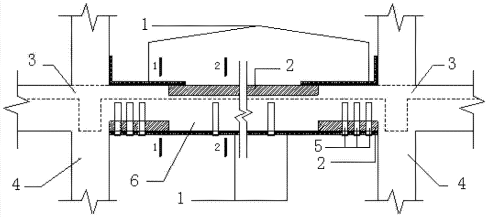
[0025] (1) Divide the beam and slab to be reinforced into two parts: the tension area and the compression area;

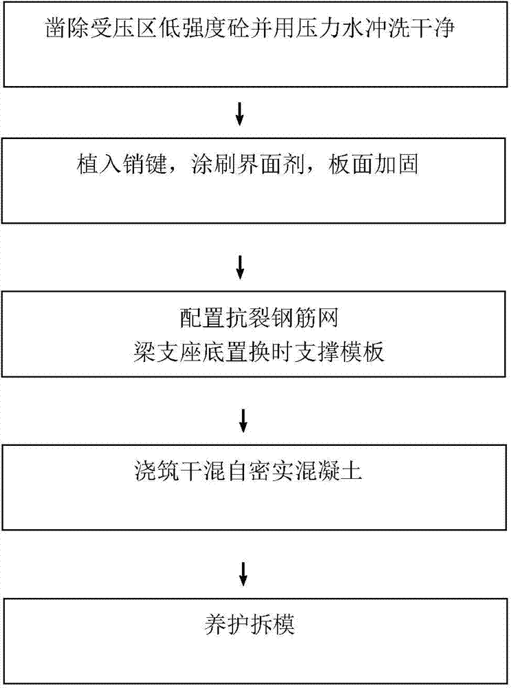
[0026] (2) Replace and reinforce the compression zone with dry-mixed self-compacting concrete, such as figure 1 As shown, the specific method is as follows: 1) Chisel out the low-strength concrete in the pressure area and rinse it with pressure water (the depth and range of chiseling are calculated and determined by a proprietary formula); 2) Insert pin keys, apply interface agent, and Reinforcement (the number of pin keys is calculated and determined by a proprietary formula); 3) Configure crack-resistant steel mesh to support the formwork when the bottom of the beam support is replaced; 4) Pouring dry-mixed self-compacting concrete (concr...


PUM


Abstract

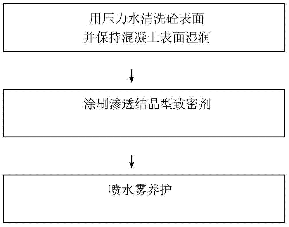
The invention discloses a method of reinforcing low-strength concrete beams and slabs. The method includes: dividing a beam-slab, to be reinforced, into two parts, namely a pull region and a stress region; subjecting the stress region to reinforcement by dry-mixed self-compacting concrete replacement; cleaning the surface of concrete of the pull region, and pasting a layer of permeable crystalline compacting agent to enhance concrete 5mm deeper in the surface of the concrete of the pull region, meeting the requirements in standards for the pasting method, and pasting carbon fiber cloth or steel plates to reinforce the pull region. The method has the advantages that the fact that the concrete with the surface pasted permeable crystalline compacting agent has higher compressive strength against concrete structure is well utilized, the structure is reinforced by the original pasting method, the durability problem of low-strength concrete is well solved by making use of compactness and water tightness in the compacting agent, and a substitution method cab be applied to low-strength concrete.

Description

technical field [0001] The invention relates to the field of strengthening of building structures, in particular to a method for strengthening low-strength concrete beams and slabs. Background technique [0002] According to the "Code for Design of Reinforced Concrete Structures" GB50010-2010, the concrete structure strength grade of plain concrete structures should not be lower than C15, and the concrete strength grade of reinforced concrete structures should not be lower than C20. "Code for Design of Concrete Structure Reinforcement" GB50367 stipulates that the strength grade of concrete reinforced by pasting carbon fiber or steel plate reinforcement method should not be lower than C15. Therefore, it is defined that a structure with a concrete strength grade lower than C15 is called a low-strength concrete structure. [0003] The main problems in low-strength concrete beams and slabs are insufficient concrete compressive capacity in the compression area, carbon fiber or st...

Claims


Application Information

Patent Timeline
IPC IPC(8): E02D23/02C04B41/45
Inventor 李延和汤建忠丁冠军
Owner NANJING UNIV OF TECH
Learn More