Micro filtering and blowing device

An air supply device and air filtering technology, which is applied in ventilation systems, space heating and ventilation, space heating and ventilation details, etc., can solve the problems that the volume cannot be further reduced, the size of the motor and the fan are large, etc.

Pending Publication Date: 2018-08-10
TIANJIN ZHONGSHI HENGYE TECH
View PDF0 Cites 0 Cited by
  • Summary
  • Abstract
  • Description
  • Claims
  • Application Information

AI Technical Summary

Problems solved by technology

[0003] Most of the existing air supply devices are fan structures, which drive the fan through the motor, and then agitate the air t

Method used


Image

  • Micro filtering and blowing device
  • Micro filtering and blowing device
  • Micro filtering and blowing device

Examples


Example Embodiment

[0021] In order to enable those skilled in the art to better understand the technical solutions of the present invention, the present invention will be further described in detail with reference to the accompanying drawings and the best embodiments.

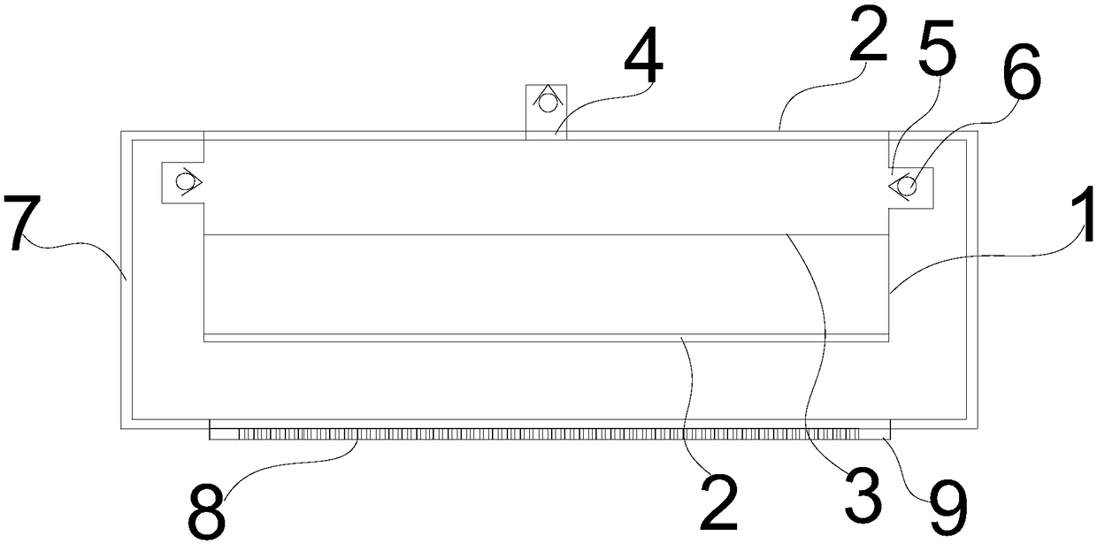
[0022] As shown in the figure, the present invention includes a casing 7 and a miniature fan arranged inside the casing, wherein:

[0023] The casing is provided with a filtered air inlet, and the air enters the casing after being filtered;
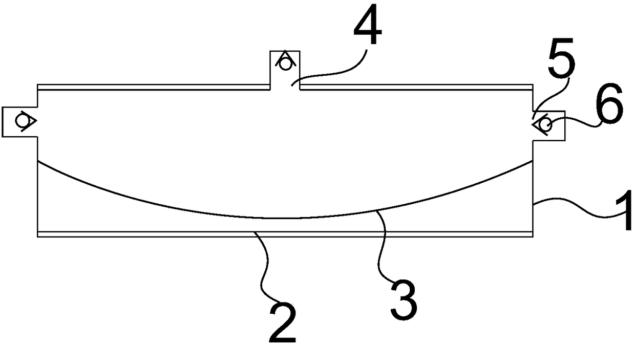
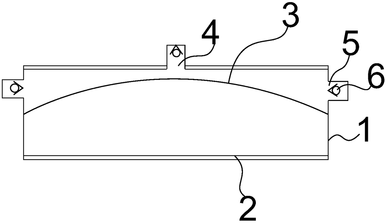
[0024] The micro-fan includes a box body 1, electrode plates 2 with opposite polarities located at both ends of the box body, and an agitating diaphragm 3 connected to the middle of the box body;

[0025] The agitating diaphragm has a polarity, and the polarities of the two electrode plates are periodically switched to each other to drive the agitating diaphragm to agitate toward the two electrode plates respectively;

[0026] One end of the box body has an air outlet 4, and the box body is provided w...


PUM


Abstract

The invention relates to a blowing device, in particular to a micro filtering and blowing device. The micro filtering and blowing device comprises a shell and a micro fan arranged in the shell, wherein a filter air inlet is formed in the shell and air filtered enters the shell; the micro fan comprises a box body, plate electrodes opposite in polarity at two ends of the box body and a blowing membrane connected to the middle part of the box body. As the micro blowing device can blow continuously and has a relatively small size, the demand of people on the micro blowing device can be met. The micro filtering and blowing device is applied to a gauze mask to blow the gauze mask actively, so that disturbance in respiration of the user is avoided.

Description

technical field [0001] The invention relates to an air supply device, in particular to a micro-filter air supply device. Background technique [0002] Masks with higher filtration grades have a more complex filter structure in order to filter pollutants, so users need to use greater suction when breathing, so it is easy for users to breathe poorly. The wind device can send the wind into the breathing position, so that the breath can be avoided. [0003] Most of the existing air supply devices are fan structures, and the motor drives the fan, and then agitates the air to flow, but both the motor and the fan have a larger size, and its specific volume cannot be further reduced, so it is still a mask. Contents of the invention [0004] The technical problem to be solved by the present invention is to overcome the deficiencies in the prior art and provide a micro-filter air supply device. [0005] The present invention is achieved through the following technical solutions: ...

Claims


Application Information

Patent Timeline
IPC IPC(8): F24F7/007F24F13/28
CPCF24F7/007F24F13/28
Inventor 李亮
Owner TIANJIN ZHONGSHI HENGYE TECH
Why Eureka
Try Eureka