Combined asynchronous induction electromagnetic coil emitter and ignition method thereof

An electromagnetic coil and combined technology, applied in the direction of the launch device, can solve the problems of insufficient smooth and stable acceleration force, high magnetic field traveling wave speed, limited application, etc., and achieve the effect of avoiding acceleration faults, smooth acceleration, and not easy to damage.

Active Publication Date: 2018-08-10
WUHAN UNIV
View PDF5 Cites 6 Cited by
  • Summary
  • Abstract
  • Description
  • Claims
  • Application Information

AI Technical Summary

Problems solved by technology

[0006] (1) The traveling wave velocity of the magnetic field required for projectile acceleration is getting higher and higher, which cannot take into account the launch efficiency and launch speed;
[0007] (2) The high-power drive coil is easy to be damaged;
[0008] (3) The acceleration force during the acceleration process of the armature of the coil transmitter is not smooth enough;
[0009] (4) Relying on a single set of synchronous induction coil transmitters is difficult to achieve propulsion with different pulse widths, amplitudes, and waveforms, and the applications in industrial and scientific fields are limited

Method used


Image

  • Combined asynchronous induction electromagnetic coil emitter and ignition method thereof
  • Combined asynchronous induction electromagnetic coil emitter and ignition method thereof
  • Combined asynchronous induction electromagnetic coil emitter and ignition method thereof

Examples


Embodiment Construction

[0044] In order to illustrate the present invention and / or the technical solutions in the prior art more clearly, the specific implementation manners of the present invention will be described below with reference to the accompanying drawings. Obviously, the accompanying drawings in the following description are only some embodiments of the present invention, and those skilled in the art can obtain other accompanying drawings based on these drawings and obtain other implementations.

[0045] It should be understood that the specific embodiments described here are only used to explain the present invention, not to limit the present invention. In addition, the technical features involved in the various embodiments of the present invention described below can be combined with each other as long as they do not constitute a conflict with each other.

[0046] It should be noted that, unless otherwise specified, the circumferential, radial, and axial directions refer to the circumfe...


PUM


Abstract

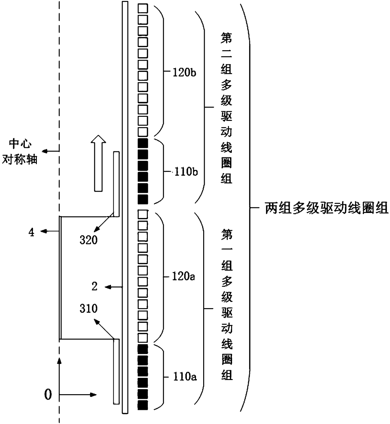
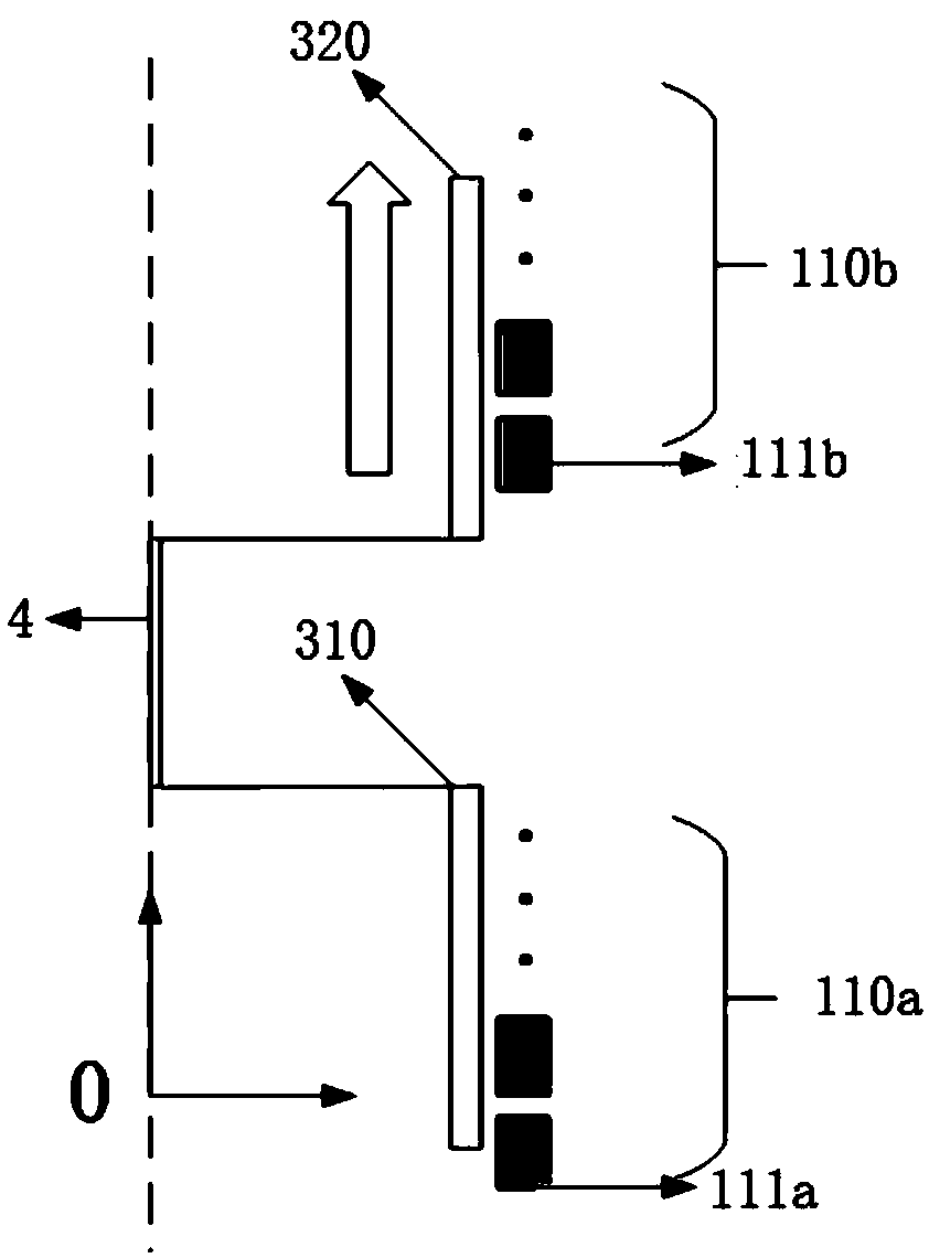
The invention discloses a combined asynchronous induction electromagnetic coil emitter and an ignition method thereof. The combined asynchronous induction electromagnetic coil emitter comprises a plurality of sets of multistage coil emitters, a gun barrel and a plurality of connectors. Each multistage coil emitter comprises a multistage driving coil set and a corresponding armature, the multistagedriving coils are sequentially wound outside the gun barrel in the axial direction of the gun barrel, the armatures are sequentially arranged in the gun barrel in the axial direction of the gun barrel, and the adjacent armatures are connected through the connectors. When the combined asynchronous induction electromagnetic coil emitter is not triggered, the armatures are located in the corresponding multistage driving coil sets. After the combined asynchronous induction electromagnetic coil emitter is triggered, the multistage driving coils provide acting force pointing to a gun opening in theaxial direction of the gun barrel for the armatures in the multistage driving coils. According to the combined asynchronous induction electromagnetic coil emitter, propulsive force of different pulsewidths, amplitudes and waveforms can be achieved, the accelerated speed faults of the armatures can be avoided, and therefore acceleration is smoother; meanwhile, stress, the emitting speed and emitting efficiency can be improved; and the combined asynchronous induction electromagnetic coil emitter is more suitable for occasions with higher requirements for thrust precision.

Description

technical field [0001] The invention relates to the technical field of launching large-mass objects such as missiles, in particular to a combined asynchronous induction electromagnetic coil launcher and an ignition method thereof. Background technique [0002] Since the velocity of the traveling wave of the magnetic field required for the acceleration of the projectile is higher and higher, the whole coil should be divided into several sections. In order to obtain traveling waves whose phase speed increases from one section to another, the frequency of the excitation power supply should be increased, or the polar distance (half wavelength) of the driving coil should be increased. The size of the pole pitch is determined by the number of phases, the length of the single-stage drive coil and the distance between the single-stage drive coils. The smaller the pole distance, the smoother the acceleration of the projectile and the greater the acceleration force. However, if the ...

Claims


Application Information

Patent Timeline
Patent Type & Authority Applications(China)
IPC IPC(8): F41F1/00
CPCF41F1/00
Inventor 张亚东龚宇佳阮江军
Owner WUHAN UNIV
Why Eureka
Try Eureka