Stepless speed change structure for planetary gears

A planetary gear, continuously variable speed technology, applied in the direction of gear transmission, belt/chain/gear, transmission parts, etc., can solve the high requirements of parts processing and lubrication, poor overload and impact resistance, and small speed change range, etc. problem, to achieve the effect of low manufacturing cost, large speed change range, and reduced maintenance cost

Inactive Publication Date: 2012-07-04
宏万兵
View PDF5 Cites 4 Cited by
  • Summary
  • Abstract
  • Description
  • Claims
  • Application Information

AI Technical Summary

Problems solved by technology

[0005] (3) Mechanical transmission, the main characteristics of mechanical transmission are: stable speed, small slip rate, reliable operation, constant power mechanical characteristics, high transmission efficiency, simple structure, convenient maintenance, and relatively cheap price; but parts processing and High lubrication requirements, low load capacity, poor overload resistance and impact resistance, so it is generally suitable for medium and small power transmission
small shifting range

Method used


Image

  • Stepless speed change structure for planetary gears
  • Stepless speed change structure for planetary gears
  • Stepless speed change structure for planetary gears

Examples


Embodiment 1

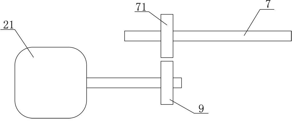
[0035] like figure 2 As shown, the power adjustment control device also includes a control motor 21 and an adjustment gear 71 installed on the control power input shaft 7. The control motor 21 includes a motor shaft 22 and a gear 9. The motor gear 23 is connected to the control power input shaft 7. The adjusting gear 71 on the input shaft 7 is connected. In this embodiment, the motor is used as the power source, and the speed of the control shaft is changed by changing the variable speed of the motor. The control motor 21 is connected with the core control unit on the automobile. Its principle is that the power source of the control power input shaft is provided by the motor, and the stepless speed change of the motor realizes the stepless speed change of the planetary gear.

Embodiment 2

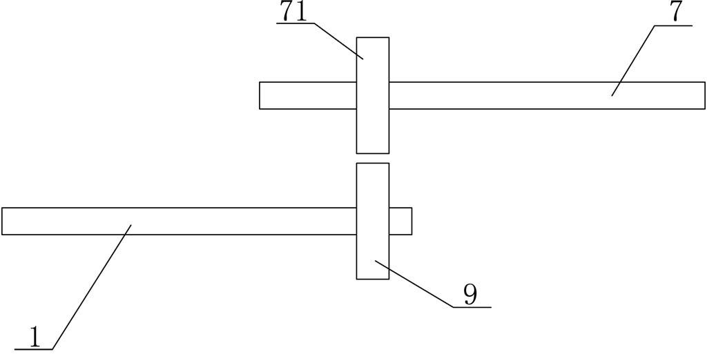
[0037] like image 3As shown, the power adjustment control device also includes a gear 9 installed on the power input shaft 1 of the automobile engine and an adjustment gear 71 installed on the control power input shaft 7 , and the gear 9 is connected to the adjustment gear 71 . In this embodiment, the power input shaft of the engine is used as the power source, and when the engine speed changes, the speed of the control shaft also changes accordingly. Its principle is that the power to control the power input shaft comes from the engine, and the change of the engine speed drives the change of the planetary gear speed.

Embodiment 3

[0039] like Figure 4 As shown, the power adjustment control device also includes a gear 9 installed on the power output shaft 12 of the automobile engine and an adjustment gear 71 installed on the control power input shaft 7 , and the gear 9 is connected to the adjustment gear 71 . In this embodiment, the power output shaft of the engine is used as the power source, and the speed of the control shaft is changed when the vehicle speed changes. Its principle is to control the power of the power input shaft from the output shaft (that is, related to the speed of the vehicle).


PUM


Abstract

The invention discloses a stepless speed change structure for planetary gears, which has the advantages of high torque bearing capability, no slipping, simple structure, less parts, low manufacture and maintenance costs, superior long service life and wide speed change range, and can be applied to heavy-duty vehicles, large-scale vehicles and mini-type vehicles. Based on the structural characteristics of the planetary gears, the stepless speed change of power input and output speeds is realized when the revolution ratio between a gear ring and a sun gear is changed by changing the rotational speed of a planetary gear rack. The stepless speed change structure comprises the gear ring, the planetary gear rack and the sun gear, wherein the gear ring is connected with the power input shaft of a vehicle engine; the sun gear is connected with the power output shaft; the planetary gears are mounted on the planetary gear rack and are connected with a power adjusting control device capable of changing the speeds of the planetary gears; and the power adjusting control device comprises a control power input shaft and a control gear arranged at one end of the control power input shaft.

Description

technical field [0001] The invention relates to a continuously variable transmission structure, in particular to a planetary gear continuously variable transmission structure. Background technique [0002] CVT is a continuously variable transmission, and its English full name is Continuous Variable Transmission, referred to as CVT. A transmission with a continuously variable transmission is also called a continuously variable transmission or continuously variable transmission. The biggest difference between this continuously variable transmission and common automatic transmission is that it saves the complex and cumbersome gear combination speed change transmission, and only uses two sets of pulleys for speed change transmission. The speed is changed by changing the contact radius between the drive wheel and the driven wheel drive belt. Since the CVT can realize the continuous change of the transmission ratio, the best match between the transmission system and the engine w...

Claims


Application Information

Patent Timeline
Patent Type & Authority Applications(China)
IPC IPC(8): F16H3/76F16H57/08
Inventor 宏万兵
Owner 宏万兵
Why Eureka
Try Eureka