Rotatably controlled electronic switch

An electronic switch and rotating disk technology, which is applied to electrical switches, circuits, and resistive elements adjusted by short-circuiting different numbers of resistive elements, can solve the problems of high manufacturing cost, complex structure of rotary switches, and high maintenance costs, and achieves the goal of manufacturing The effect of low cost and maintenance cost, simple structure and convenient operation

Inactive Publication Date: 2018-08-10
佛山杰致信息科技有限公司
View PDF0 Cites 1 Cited by
  • Summary
  • Abstract
  • Description
  • Claims
  • Application Information

AI Technical Summary

Problems solved by technology

[0003] Most of the existing rotary switches have complex str

Method used


Image

  • Rotatably controlled electronic switch
  • Rotatably controlled electronic switch
  • Rotatably controlled electronic switch

Examples


Embodiment Construction

[0017] The following will clearly and completely describe the technical solutions in the embodiments of the present invention with reference to the accompanying drawings in the embodiments of the present invention. Obviously, the described embodiments are only some, not all, embodiments of the present invention.

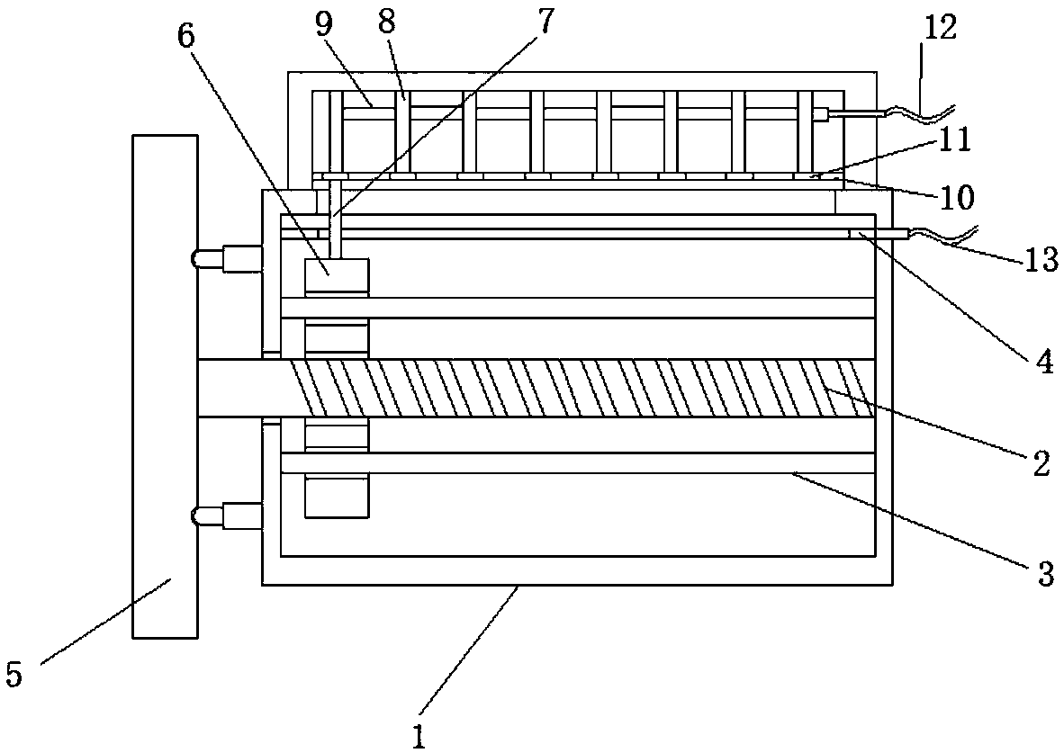
[0018] refer to Figure 1-3 , a rotatably controlled electronic switch, comprising a casing 1, a horizontally arranged threaded rod 2 is installed in the casing 1, and a vertically arranged moving plate 6 is mounted on the outer thread of the threaded rod 2, and one end of the threaded rod 2 extends to Outside the casing 1, two guide holes are provided on the moving plate 6, and two horizontally arranged guide rods 3 are fixedly installed in the casing 1, and the guide rods 3 penetrate the moving plate 6 through the guide holes, and the horizontally arranged guide rods 3 are fixedly installed in the casing 1. The metal strip 4 is located above the moving plate 6, and...


PUM


Abstract

The invention discloses a rotatably controlled electronic switch. The rotatably controlled electronic switch comprises a shell; a horizontally arranged threaded rod is rotatably installed in the shell; a vertically arranged movable plate is in threaded installation outside the threaded rod; one end of the threaded rod extends to the exterior of the shell; two guide holes are formed in the movableplate; two horizontally arranged guide rods are fixedly installed in the shell; the guide rods pass through the movable plate through the guide holes; a horizontally arranged metal strip is fixedly installed in the shell; the metal strip is positioned over the movable plate; furthermore, a first sliding opening is formed in the metal strip; a second sliding opening is formed on the top of the shell; the first sliding opening corresponds to the second sliding opening; an installation cover is fixedly installed on the top of the shell; a vertically arranged metal rod is fixedly installed on thetop of the movable plate; and the top of the metal rod extends into the installation cover through the first sliding opening and the second sliding opening. The rotatably controlled electronic switchdisclosed by the invention is smart in structure, simple in structure, convenient to operate and low in manufacturing cost and maintenance cost, and has the multi-level adjustment effect.

Description

technical field [0001] The invention relates to the technical field of switches, in particular to a rotatably controlled electronic switch. Background technique [0002] The rotary switch can be used to replace the rotary pulse generator with the analog function of the traditional resistive potentiometer. These rotary switches are usually used in the man-machine interface of the front panel of the instrument and the audio-visual control panel. The rotary switch uses an orthogonal optical encoder to replace the analog potentiometer. A pure digital device, these rotary switches look similar to traditional or resistive potentiometers in appearance, but the internal construction of these rotary switches is completely digital and uses optical technology. Similar to traditional incremental encoder products, there are two quadrature output signals (channel A and channel B), which can be directly connected to the encoder processing chip. [0003] Most of the existing rotary switche...

Claims


Application Information

Patent Timeline
IPC IPC(8): H01H3/02H01C10/06H01C10/38
CPCH01H3/0213H01C10/06H01C10/38
Inventor 王玉环
Owner 佛山杰致信息科技有限公司
Why Eureka
Try Eureka