
oscillator

An oscillator, eccentric shaft technology, applied to oscillators. It can solve the problems of the unadjustable center of gravity of the oscillator and the low maximum height of the liquid in the liquid storage bottle, so as to improve the vibration effect, avoid excessive or insufficient vibration, and moderate the collision force.

Active Publication Date: 2020-05-26
浙江兆华机械制造有限公司
View PDF1 Cites 2 Cited by
  • Summary
  • Abstract
  • Description
  • Claims
  • Application Information

AI Technical Summary

Problems solved by technology

[0004] The object of the present invention is to provide an oscillator, which solves the problem that the center of gravity of the oscillator used by the existing oscillator cannot be adjusted. When there is too much or too little liquid in the liquid storage bottle, the single counterweight The position of the center of gravity will make the maximum floating height of the liquid in the liquid storage bottle too low or too high

Method used


Image

  • oscillator
  • oscillator
  • oscillator

Examples


Embodiment 1

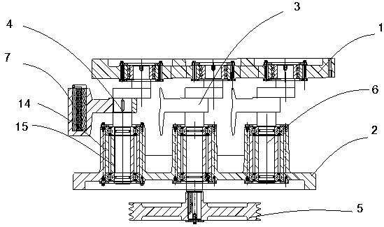
[0027] Embodiment 1: The present invention provides an oscillator, including: an upper plate of the oscillator 1; a lower plate of the oscillator 2, located directly below the upper plate of the oscillator; an active eccentric shaft 3, one end of which is rotated and installed on the upper plate of the oscillator, and One side is rotatably installed on the lower plate of the oscillator, and its end protrudes downward from the active eccentric shaft and is fixedly connected to the driven pulley 5; the driven eccentric shaft 6 is rotatably installed on the upper plate of the oscillator, and the other end is rotatably installed on the oscillator The lower plate; a plurality of counterweights 7 are detachably installed on the active eccentric shaft and the driven eccentric shaft respectively; the counterweights are arc-shaped cylinders; at least one of them is located on the driven eccentric shaft A plurality of parallel installation grooves 8 are formed in the downward depression ...

Embodiment 2

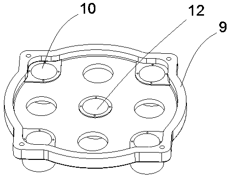
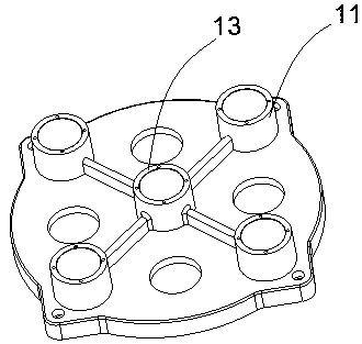
[0028] Embodiment 2: as figure 1 , figure 2 , image 3 , Figure 4 As shown, the present invention provides an oscillator, comprising: an upper plate of the oscillator; a lower plate of the oscillator, located directly below the upper plate of the oscillator; an annular flange 9 is also provided on the bottom surface of the lower plate of the oscillator; The top surface of the lower plate of the oscillator is also provided with several first through holes 10, the upper side of the first through holes is provided with a first bushing 11, and the inner cavity of the first bushing communicates with the first through hole; A second through hole 12 is provided in the center of the top surface of the lower plate of the oscillator, and a second bushing 13 is provided on the upper side of the second through hole, and the inner cavity of the second bushing communicates with the second through hole. The first through holes are uniformly arranged on the outer periphery of the second ...


PUM


Abstract

The invention provides an oscillator, comprising: an upper plate of the oscillator; a lower plate of the oscillator, which is located directly below the upper plate of the oscillator; The lower plate, the end of which protrudes downward from the active eccentric shaft and is fixedly connected to the driven pulley; the driven eccentric shaft, one end is rotatably installed on the upper plate of the oscillator, and the other end is rotatably installed on the lower plate of the oscillator; multiple counterweights, Respectively detachably installed on the active eccentric shaft and the driven eccentric shaft; the counterweight is an arc-shaped column; at least one of the counterweights on the driven eccentric shaft faces downwards and forms several There are two parallel installation slots, and a center-of-gravity adjustment plate matching the installation slots is placed in the installation slots. The invention avoids the excessive or insufficient oscillation of the sample solution; at the same time, the collision force between the drug particles or microorganisms in the liquid and the bottle wall is moderate.

Description

technical field [0001] The invention relates to the field of oscillator accessories, in particular to oscillators. Background technique [0002] The existing patent application number is CN200920112059.4 "torrent oscillator" patent document, which discloses a torrent oscillator, the center of gravity of the oscillator used in practice cannot be adjusted, when the liquid storage bottle When the liquid is too much or too little, the position of the center of gravity of a single counterweight will make the maximum height of the liquid in the liquid storage bottle float too low or too high, and the collision force between the drug particles or microorganisms in the liquid and the bottle wall will be too high. Small or too large, reduces the oscillation effect. Contents of the invention [0003] (1) Technical problems to be solved [0004] The object of the present invention is to provide an oscillator, which solves the problem that the center of gravity of the oscillator use...

Claims


Application Information

Patent Timeline
Patent Type & Authority Patents(China)
IPC IPC(8): B01F11/00
CPCB01F31/20
Inventor 曹黎军郑军
Owner 浙江兆华机械制造有限公司
Learn More