
Unmanned aerial vehicle wing multidirectional-locking mechanism

A locking mechanism, multi-directional technology, applied in the field of unmanned aerial vehicles, can solve problems such as unintended take-off and accidents of unmanned aerial vehicles

Active Publication Date: 2018-08-14
金华新创力科技有限公司
View PDF4 Cites 1 Cited by
  • Summary
  • Abstract
  • Description
  • Claims
  • Application Information

AI Technical Summary

Problems solved by technology

[0002] UAV is an unmanned aircraft controlled by radio remote control equipment and its own program control device. There is no cockpit on board, but it is equipped with autopilot, program control device and other equipment. Radar and other equipment, for tracking, positioning, remote control, telemetry and digital transmission, can take off like an ordinary plane under radio control or launch it with a booster rocket, or it can be brought into the air by the mother plane to fly. When it is recovered, it can be used It automatically lands in the same way as the landing process of ordinary aircraft, and can also be recovered by remote control with a parachute or a block. When the drone is not in use, the wings are in a loose state, and when the switch is touched, it is easy to cause the drone to take off accidentally. cause unnecessary accidents

Method used


Image

  • Unmanned aerial vehicle wing multidirectional-locking mechanism
  • Unmanned aerial vehicle wing multidirectional-locking mechanism
  • Unmanned aerial vehicle wing multidirectional-locking mechanism

Examples


Embodiment Construction

[0017] The following will clearly and completely describe the technical solutions in the embodiments of the present invention with reference to the accompanying drawings in the embodiments of the present invention. Obviously, the described embodiments are only some, not all, embodiments of the present invention. Based on the embodiments of the present invention, all other embodiments obtained by persons of ordinary skill in the art without making creative efforts belong to the protection scope of the present invention.

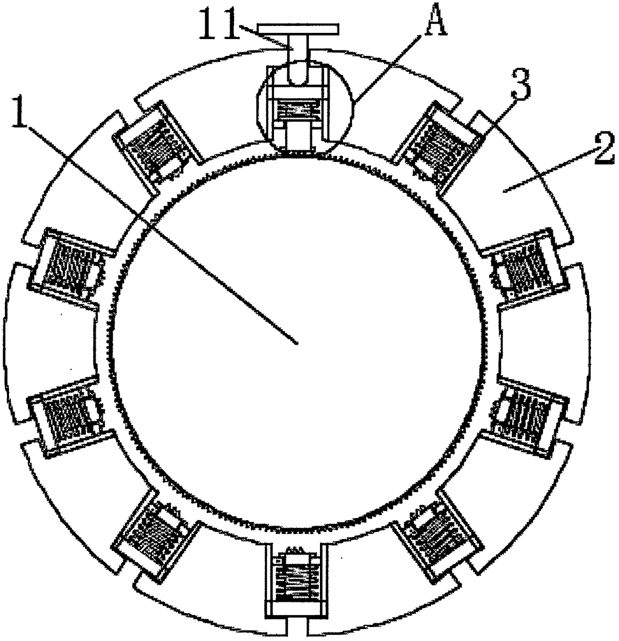
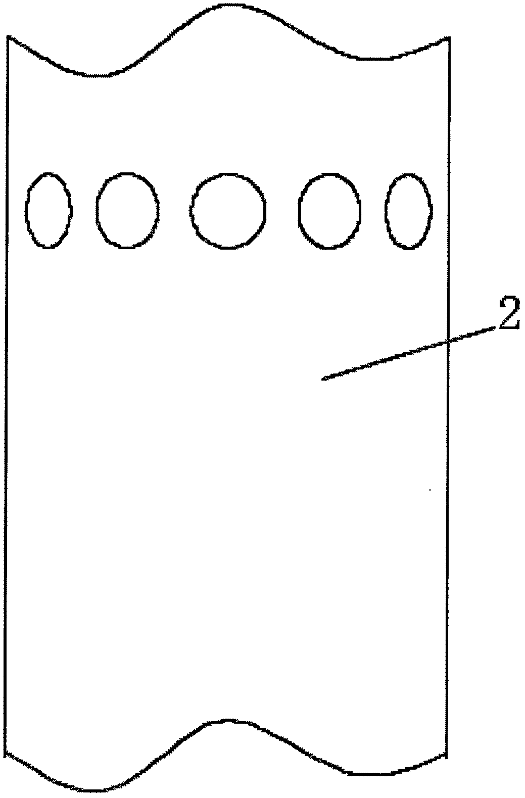
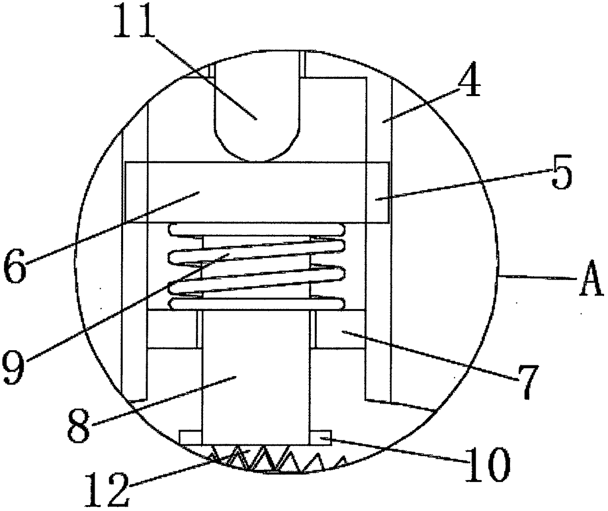
[0018] see Figure 1-3 , the present invention provides a technical solution: a multi-directional locking mechanism for the wing of an unmanned aerial vehicle, including a wing shaft 1 and a ring protective cover 2, a cylindrical groove 3 is opened on the inner side of the ring protective cover 2, and The bottom of the cylindrical groove 3 is provided with a threaded hole perpendicular to the bottom of the cylindrical groove 3, the cylindrical groove 3 is prov...


PUM


Abstract

The invention discloses an unmanned aerial vehicle wing multidirectional-locking mechanism. The unmanned aerial vehicle wing multidirectional-locking mechanism comprises a wing rotating shaft and an annular protection sleeve, cylindrical grooves are arranged at the inner side of the annular protection sleeve, the groove bottom of every cylindrical groove is provided with a threaded hole perpendicular to the groove bottom of the cylindrical groove, a pressure plate is arranged in every cylindrical groove, a fixed circular ring perpendicular to the groove wall of every cylindrical groove is arranged at the outer side of the pressure plate, the sidewall of the fixed circular ring is fixedly connected with the inner wall of the corresponding cylindrical groove, a return spring is arranged between the pressure plate and the fixed circular ring, two ends of the return spring are respectively fixedly connected with the inner side of a limiting circular ring and the outer side of the pressureplate, a telescopic rod is arranged in the circular hole of the fixed circular ring, one end of the telescopic rod goes through the return spring and is fixedly connected with the middle part of the outer side of the pressure plate, the other end of the telescopic rod goes through the circular hole of the fixed circular ring and reaches the external of the circular groove, and vertical chutes arearranged in two sides of every circular groove to make the wing locked in multiple directions.

Description

technical field [0001] The invention relates to the field of unmanned aerial vehicles, in particular to a multi-directional locking mechanism for the wings of an unmanned aerial vehicle. Background technique [0002] UAV is an unmanned aircraft controlled by radio remote control equipment and its own program control device. There is no cockpit on board, but it is equipped with autopilot, program control device and other equipment. Radar and other equipment, for tracking, positioning, remote control, telemetry and digital transmission, can take off like an ordinary plane under radio control or launch it with a booster rocket, or it can be brought into the air by the mother plane for flight. When it is recovered, it can be used It automatically lands in the same way as an ordinary aircraft landing process, and can also be recovered by remote control with a parachute or a block. When the drone is not in use, the wings are in a loose state. When the switch is touched, the drone ...

Claims


Application Information

Patent Timeline
Patent Type & Authority Applications(China)
IPC IPC(8): B64C3/00B64D45/00
CPCB64C3/00B64D45/00
Inventor 倪惠芳
Owner 金华新创力科技有限公司
Learn More