Carriage positioning method and positioning device

A positioning method and technology of positioning device, which are applied to measurement devices, optical devices, instruments, etc., can solve the problems of lack of waterproof measures for laser sensors, poor installation of sensors, interference of vehicles, etc., and achieve rapid positioning and measurement results. Accurate, cost-reduced results

Active Publication Date: 2018-08-14
HUNAN SUNDY SCI & TECH DEV
View PDF32 Cites 4 Cited by
  • Summary
  • Abstract
  • Description
  • Claims
  • Application Information

AI Technical Summary

Problems solved by technology

The disadvantages of this solution are: the front and rear directions of O1 and O3 are exactly the driving direction of the car, the position of the sensor is not easy to install, and it is easy to interfere with the car
In addition, a single laser sensor costs about 3,000 yuan, and four add up to 12,000. The cost is too high. The laser sensor is installed outdoors without waterproof measures, and it cannot be adopted in practical applications.

Method used


Image

  • Carriage positioning method and positioning device
  • Carriage positioning method and positioning device
  • Carriage positioning method and positioning device

Examples


Embodiment 1

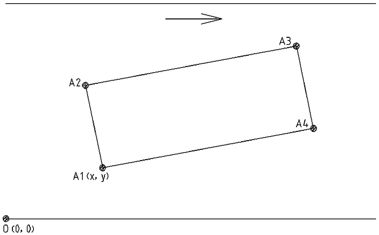
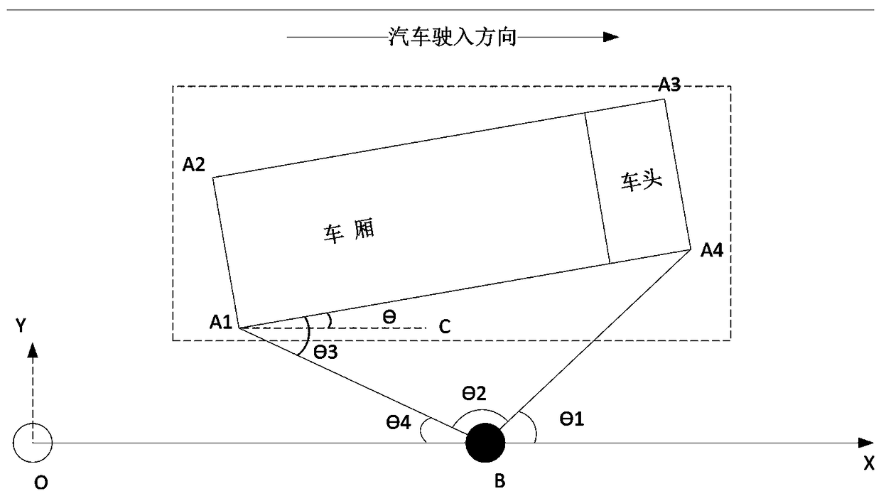
[0030] Embodiment one: if image 3 As shown, the compartment positioning method of the present embodiment includes the following steps: S1. At the scanning origin, a side of the compartment is scanned through the horizontal rotation of the sensor, and the distances between at least two scanning points on the side and the scanning origin are obtained respectively. And the corresponding scanning angle, at least one of the scanning points is an endpoint; S2. Calculate and determine the coordinates of the endpoint and the declination angle of the carriage according to the distance and angle; S3. Determine the carriage according to the preset vehicle model data, as well as the coordinates and declination of the endpoint s position. A complete scan is performed on the side, with two scan points, both of which are endpoints. The scanning origin is located in the middle of one side of the car's parking reference area. First construct the scanning coordinate system according to the s...

Embodiment 2

[0040] Embodiment 2: The positioning method of this embodiment is basically the same as that of Embodiment 1, the difference is that: the side is scanned incompletely, two scanning points are used, and one scanning point is an end point. Another scanning point is preferably a scanning point corresponding to the scanning start position.

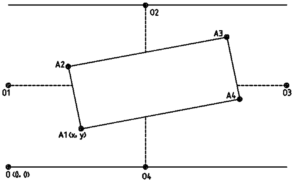
[0041] Such as Figure 4 As shown, compared with Embodiment 1, the scanning initial position of the scanning sensor in this embodiment is not in the direction of the X-axis in the positioning coordinate system, but has a certain angle in the counterclockwise direction relative to the X-axis, such as Figure 4 As shown in , the initial position is the direction of the Y axis, that is, the angle is 90 degrees. Of course, it can also be less than 90 degrees. For example, the initial position is the position indicated by BD. The initial position is determined according to the actual situation, and the purpose is to further reduce the scanning ran...


PUM


Abstract

The invention discloses a carriage positioning method and device. The method comprises the following steps: S1, scanning the side surface of the carriage through the horizontal rotation of the sensorat the scanning origin, and obtaining at least two scanning points on the side surface, the distance between at least two scanning points, and the corresponding scanning angle, wherein at least one ofthe scanning points is an end point; S2, determining the coordinates of the end point and the deflection angle of the carriage according to the distance and angle calculation; S3, according to the preset vehicle model data, the coordinates of the end point and the deflection angle, determining the position of the carriage. The positioning device has the advantages of being high in positioning precision, high in positioning speed, and low in cost.

Description

technical field [0001] The invention relates to the field of car compartment positioning, in particular to a compartment positioning method and a positioning device, and is especially applied to positioning the compartment during the sampling process of a transport vehicle. Background technique [0002] In the process of generating the sampling points of the automobile sampling machine, the sampling points are randomly generated in the whole range of the compartment. In the actual implementation process, the reference coordinates in the algorithm for generating sampling points are the origin of the compartment, not the origin of the sampling head, and the actual sampling coordinates are based on The origin of the sampling head is used as a reference, so that the parking position and deflection angle of the vehicle directly affect the coordinates of the generated sampling points. In the actual application process, if the accurate positioning of the vehicle cannot be achieved,...

Claims


Application Information

Patent Timeline
Patent Type & Authority Applications(China)
IPC IPC(8): G01B11/00G01B11/26
CPCG01B11/00G01B11/002G01B11/26
Inventor 谭为任率
Owner HUNAN SUNDY SCI & TECH DEV
Why Eureka
Try Eureka