
An anchor device and anchor system against osteoporosis

An anchor and bone technology, applied in the directions of nails, U-shaped nails, surgical fixation nails, etc., can solve the problems of weakening the tensile strength of anchors, and achieve the effects of improving the pulling force, high stability, and preventing cutting out.

Active Publication Date: 2018-11-02
SHANGHAI KINETIC MEDICAL +1
View PDF8 Cites 0 Cited by
  • Summary
  • Abstract
  • Description
  • Claims
  • Application Information

AI Technical Summary

Problems solved by technology

[0004] However, the existing threaded anchors are not particularly aimed at patients with osteoporosis. For patients with osteoporosis, due to their low bone density, during the implantation period, the anchors will lose their tensile strength due to the continuous loss of bone loss. Gradually weaken until loose

Method used


Image

  • An anchor device and anchor system against osteoporosis
  • An anchor device and anchor system against osteoporosis
  • An anchor device and anchor system against osteoporosis

Examples


Embodiment 1

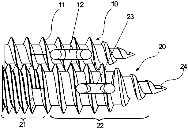
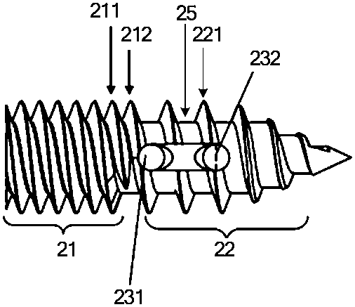
[0038] Please refer to figure 1 and figure 2 ,Such as figure 1 and figure 2 As shown, the anchor device against osteoporosis provided by the embodiment of the present invention includes a pressure anchor 10 and a tension anchor 20 matched with each other through external threads, and the pressure anchor 10 and the tension anchor 20 both include anchors The main body (such as the tension anchor 20 includes the anchor body 25, the anchor body of the compression anchor 10 is not marked), the anchor body is provided with an inner cavity extending along its longitudinal direction, and the anchor body is also provided with sutures connection structure ( figure 1 The symbols 12 and 23 respectively represent the suture connection structure set on the pressure anchor 10 and the suture connection structure set on the tension anchor 20), the suture connection structure is set at the front end of the anchor body, so that the anchor The outside of the body is provided with a full thr...

Embodiment 2

[0053] The difference between this embodiment and embodiment 1 is:

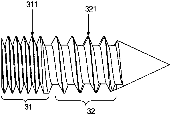
[0054] see image 3 , the cancellous bone thread 32 and the cortical bone thread 31 are both provided with a single-start thread. Specifically, the cancellous bone thread 32 is provided with a fourth thread 321 , the cortical bone thread 31 is provided with a fifth thread 311 , and the pitch of the fourth thread 321 is larger than that of the fifth thread 311 .

[0055] Other aspects of Embodiment 2 are the same as those of Embodiment 1, and will not be repeated here.

[0056] The present invention also provides an anchor system against osteoporosis, the anchor system includes a driving tool and the anchor device against osteoporosis described in the above-mentioned embodiment 1 or embodiment 2, the driving tool can be combined with the Compatible with the inner cavity.


PUM


Abstract

The invention discloses an anchor bolt device for resisting osteoporosis. The anchor bolt device is provided with two stages of anti-drawing mechanisms. According to the first stage of anti-drawing mechanism, the anchor bolt device for resisting osteoporosis comprises a pressure anchor bolt and a tension anchor bolt which are matched with each other through external threads, and the tension anchorbolt is used for bearing the reverse force when the pressure anchor bolt is pressurized so as to increase the drawing force of the anchor bolt device. According to the second-stage of anti-drawing mechanism, a full-thread structure of the tension anchor bolt comprises a cancellous bone thread on the front portion of an anchor bolt body and a cortical bone thread on the rear portion of the anchorbolt body, and the pitch of the cancellous bone thread is larger than that of the cortical bone thread. Due to the two stages of anti-drawing mechanisms, the anchor bolt device for resisting osteoporosis has good drawing force, and is particularly suitable for patients suffering from osteoporosis. The invention further discloses an anchor bolt system for resisting osteoporosis.

Description

technical field [0001] The invention relates to the technical field of medical equipment, in particular to an anchor device and an anchor system for fighting against osteoporosis. Background technique [0002] Complete or partial separation of ligaments, tendons, and / or other soft tissues from their associated bone in the body is a relatively common injury, especially among athletes. Such injuries are often the result of excessive stress being exerted on these tissues, for example, in accidents resulting from falls, productive activities, overexertion during sports competition, or in any number of other situations. [0003] At present, clinically, for cases of complete separation and some cases of partial separation, the soft tissue and bone are generally reconnected by anchors with wires, and the anchors are embedded in the bone to fix the torn tendon tissue so as to achieve tendon-bone healing. Purpose. [0004] However, the existing threaded anchors are not particularly...

Claims


Application Information

Patent Timeline
Patent Type & Authority Patents(China)
IPC IPC(8): A61B17/064A61B17/04
CPCA61B17/0401A61B17/0642A61B2017/0408
Inventor 赖卫国肖诗梁俞威
Owner SHANGHAI KINETIC MEDICAL
Learn More