Sludge agitator

A stirring device and sludge technology, applied in mixers with rotary stirring devices, mixer accessories, transportation and packaging, etc., can solve problems such as uneven stirring of sludge, and achieve simple structure, accelerated flow mixing, and simple operation. Effect

Inactive Publication Date: 2018-08-17
湖州南浔亿康机械有限公司
View PDF7 Cites 0 Cited by
  • Summary
  • Abstract
  • Description
  • Claims
  • Application Information

AI Technical Summary

Problems solved by technology

[0004] In order to solve the defect of uneven stirring of the sludge at the bottom of the stirring tank in the prior art, the present invention provides a sludge stirring device

Method used


Image

  • Sludge agitator
  • Sludge agitator

Examples


Embodiment Construction

[0015] In order to make the technical means, creative features, goals and effects achieved by the present invention easy to understand, the present invention will be further described below in conjunction with specific embodiments.

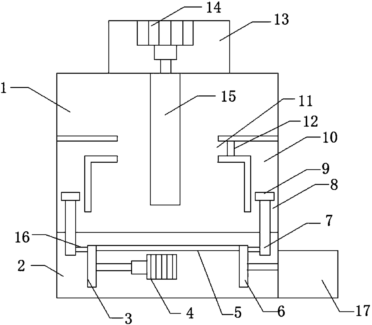
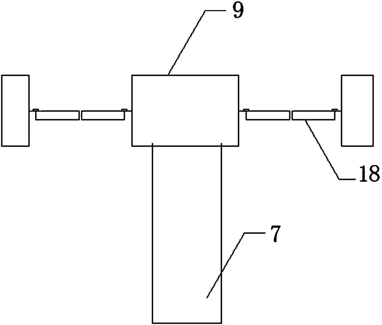
[0016] like Figure 1-2 As shown, a sludge stirring device includes a mixing box 1 and a control room 2. The inner walls of both sides of the mixing box 1 are provided with push grooves 10, one end of the push groove 10 is the groove inlet 8, and the other end of the push groove 10 is It is the groove outlet 11, the inside of the push groove 10 is provided with a push rod 7, one end of the push rod 7 is fixedly connected with a push plate 9, the other end of the push rod 7 is located in the control room 2, and the control room 2 is located at the bottom of the mixing box 1, and the control room 2 There is a first motor 4 inside, the output shaft of the first motor 4 is fixedly connected with the center of the driving wheel 3 through the rotating r...


PUM


Abstract

The invention discloses a sludge agitator, which comprises an agitating tank and a control chamber, the internal walls of both sides of the agitating tank are provided with push channels, one end of each push channel is a channel inlet, the other end of each push channel is a channel outlet, push rods are arranged inside the push channels, a push plate is fixedly connected to one end of each pushrod, the other ends of the push rods are located in the control chamber, the control chamber is located on the bottom of the agitating tank, and a first motor is arranged inside the control chamber. According to the invention, by arranging the push channels in the corners of bottom of the agitating tank and arranging the push rods inside the push channels, sludge which is located on the bottom andcannot be reached by an agitating rod or located at positions where the sludge can hardly be agitated can be pushed to be beside the agitating rod by the push rods and agitated, consequently, the sludge in the whole agitating tank can be sufficiently agitated, and meanwhile, the flow and mixing of the sludge in the agitating tank can be accelerated as well. The structure of the sludge agitator issimple, the sludge agitator is easy to operate, the cost is low, and sludge can be sufficiently agitated.

Description

technical field [0001] The invention relates to the field of environmental protection, in particular to a sludge stirring device. Background technique [0002] Sludge treatment is the process of reducing, stabilizing and harmlessly treating sludge. The higher the degree of sewage treatment, the more sludge residues will be generated to be treated, unless land treatment or sewage ponds are used Otherwise, general sewage treatment plants must be equipped with sludge treatment facilities. For modern sewage treatment plants, sludge treatment and disposal have become the most complicated and costly part of the sewage treatment system. [0003] Generally, there is a sludge stirring device in the sludge digester, but the stirring rod can only stir the sludge located in the middle of the sludge digester, and the sludge located at the bottom and corners of the sludge is often in a state of sedimentation and cannot be fully stirred. Stirring is not conducive to the post-purification ...

Claims


Application Information

Patent Timeline
Patent Type & Authority Applications(China)
IPC IPC(8): B01F7/16B01F15/00
CPCB01F27/80B01F35/53
Inventor 顾旭峰
Owner 湖州南浔亿康机械有限公司
Why Eureka
Try Eureka