

Crankshaft surface cleaning device
A surface cleaning and crankshaft technology, applied in cleaning methods and utensils, cleaning methods using tools, cleaning methods using liquids, etc., can solve the problems of incomplete cleaning, light labor, etc., and achieve no cleaning dead ends and comprehensive cleaning , good cleaning effect
Pending Publication Date: 2018-08-17
重庆伟福机械有限公司
View PDF0 Cites 9 Cited by
- Summary
- Abstract
- Description
- Claims
- Application Information
AI Technical Summary
Problems solved by technology
The engine crankshaft needs to be cleaned after manufacture and before assembly to ensure good work after assembly to the engine. Now it is usually cleaned manually, but manual cleaning has the disadvantages of incomplete cleaning and light labor.
Method used
View moreImage
Smart ImageViewing Examples

Examples
Embodiment Construction
[0016] The present invention will be described in further detail below by means of specific embodiments:
Login to View More PUM
 Abstract
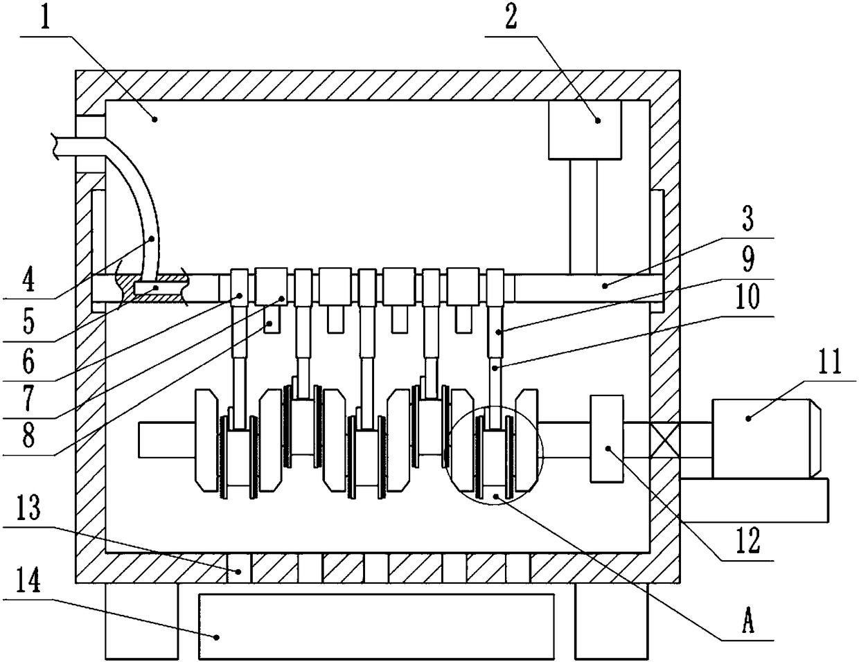
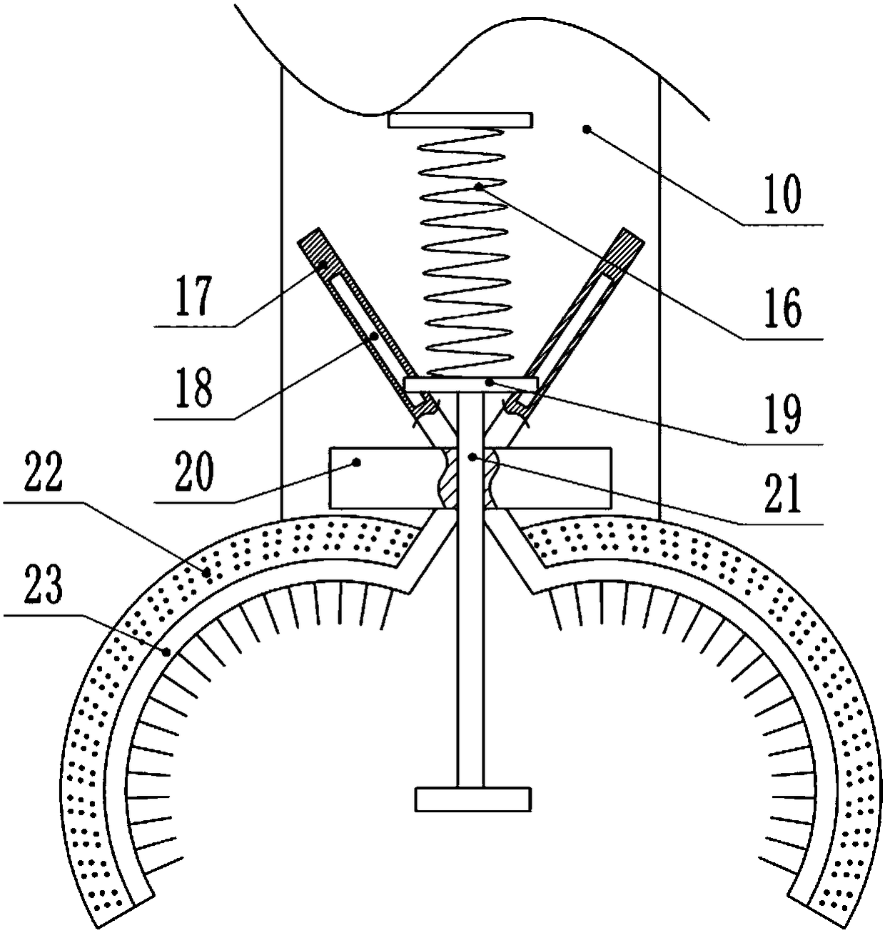
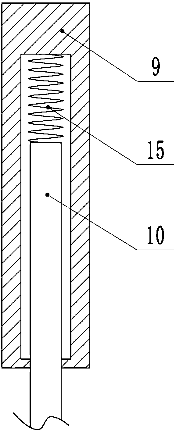
The invention belongs to the technical field of cleaning equipment, and particularly discloses a crankshaft surface cleaning device. The crankshaft surface cleaning device comprises a box body. The box body is internally provided with a clamping mechanism for clamping a crankshaft, a power mechanism for driving the clamping mechanism to rotate, and a cleaning mechanism for cleaning the crankshaft.The cleaning mechanism comprises a horizontally-arranged support rod, a lifting mechanism for driving the support rod to lift and lower is arranged on the box body, the support is provided with a plurality of screws, and the screws are provided with elastic telescopic rods. Screw holes matched with the screws are formed in the upper ends of the elastic telescopic rods, and holding claw mechanismscapable of holding a journal of the crankshaft are arranged at the lower ends of the elastic telescopic rods. Brushing bristles are arranged on the inner sides and the left and right sides of the holding claw mechanisms, and the box body is internally provided with a plurality of spraying mechanisms for spraying water on the crankshaft. The crankshaft is cleaned by the brushing bristles moving back and forth, the cleaning dead angle is avoided and the cleaning effect is better.
Description
technical field [0001] The invention belongs to the technical field of cleaning equipment, in particular to a crankshaft surface cleaning device. Background technique [0002] The crankshaft is the most important component in the engine. It bears the force transmitted by the connecting rod and converts it into torque through the crankshaft output and drives other accessories on the engine to work. The crankshaft is subjected to the joint action of the centrifugal force of the rotating mass, the periodically changing gas inertial force and the reciprocating inertial force, so that the crankshaft is subjected to the bending torsional load. Therefore, the crankshaft is required to have sufficient strength and rigidity, and the surface of the journal needs to be wear-resistant, work evenly, and have good balance. The engine crankshaft needs to be cleaned after manufacture and before assembly to ensure good work after assembly to the engine. Nowadays, it is usually cleaned manu...
Claims
Login to View More Application Information
Patent Timeline
 Patent Type & AuthorityApplications(China)
IPC IPC(8): B08B3/02B08B1/02B08B3/08B08B13/00
CPCB08B3/022B08B3/08B08B13/00B08B1/12B08B1/20
Inventor黄伟
Owner重庆伟福机械有限公司