Supercharge Your Innovation With Domain-Expert AI Agents!

A manufacturing method of a lightweight new energy vehicle drive motor shaft

A technology for new energy vehicles and drive motors, applied in vehicle parts, transportation and packaging, etc., can solve the problems of increasing the weight of the rotating shaft, waste, and long processing time, and achieve reduced machining costs, improved utilization, and high hole forming accuracy Effect

Active Publication Date: 2020-08-25
CHONGQING CHUANGJING WARM FORGING FORMING
View PDF5 Cites 0 Cited by
  • Summary
  • Abstract
  • Description
  • Claims
  • Application Information

AI Technical Summary

Problems solved by technology

Since the bearing moment of the motor shaft is very large, reaching 200-350N meters, the diameter of the shaft is relatively large. In the existing structure, it is usually increased to φ50-80mm, but the increase in diameter also increases the weight of the shaft correspondingly. The transmission of power and rotation will have a relatively large adverse effect, and its own weight needs to be reduced; in the prior art, the weight of the shaft is reduced by drilling the center hole, but after the motor shaft is formed, the hole is drilled by machining, first of all A lot of materials are wasted, which reduces the utilization rate of materials; secondly, the processing time consumed by machining is more, which increases the machining cost of the shaft; , such as a structure with a large inner hole in the middle and small holes at both ends, the inner hole cannot be processed by drilling and boring machining, and its matching and installation structure are limited, which limits the scope of use of the motor shaft; therefore, the existing motor The machining methods of the rotating shaft and drilling and boring cannot meet the needs of the market

Method used


Image

  • A manufacturing method of a lightweight new energy vehicle drive motor shaft
  • A manufacturing method of a lightweight new energy vehicle drive motor shaft
  • A manufacturing method of a lightweight new energy vehicle drive motor shaft

Examples


Embodiment Construction

[0027] Below in conjunction with accompanying drawing and specific embodiment, the present invention is described further;

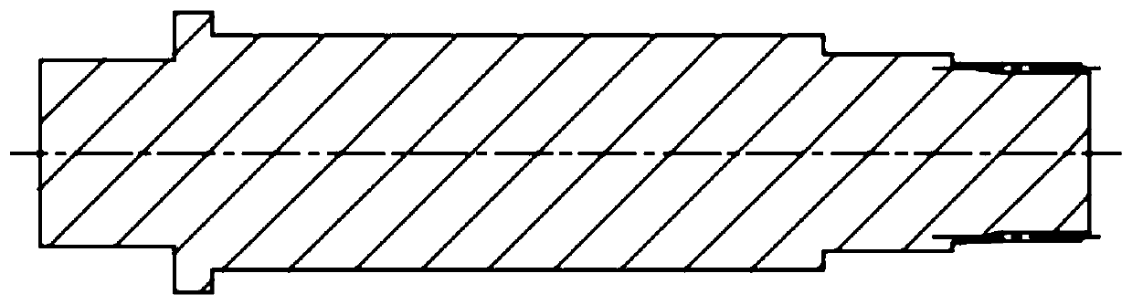
[0028] Such as figure 1 As shown, due to the limitation of processing technology and difficulty, the traditional motor shaft does not design the inner hole, resulting in a solid structure in the middle, which consumes more raw materials; and adopts machining methods such as drilling and boring in the prior art, result in higher costs.

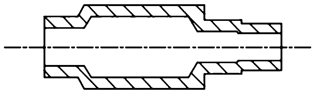
[0029] Such as figure 2 As shown, the hollow motor rotating shaft obtained by the present invention has a central inner hole, and the cavity of the inner hole is large in the middle part and small at both ends. Large, so that the wall thickness of this part of the cylinder is basically uniform with the wall thickness of other parts; this structure with a substantially uniform wall thickness cannot be processed by the machining drilling and boring methods in the prior art.

[0030] Such as Figure 3-1 , 3-2 , 3-3, 4-...


PUM

PropertyMeasurementUnit
hardnessaaaaaaaaaa

Abstract

The invention discloses a manufacturing method for a light rotating shaft of a driving motor of a new energy vehicle. The manufacturing method comprises the steps that (1) blanking is carried out; (2)a pipe is placed in a first sequential extrusion die, a core shaft penetrates into an inner hole of the pipe, and an inner round hole and an outer circumferential surface at the right end of the rotating shaft of the motor are extruded; (3) a blank is placed in a second sequential extrusion die, a step core shaft is adopted, and the right end surface and two step-shaped outer circumferential surfaces at the right end of the rotating shaft of the motor are extruded; (4) the heated or partially heated blank is placed in a third sequential extrusion die, a third core shaft is adopted, an outer circular and an inner hole at the left end of the rotating shaft of the motor are extruded by hot forging, and the heating temperature is 900 DEG C + / -50 DEG C; (5) steps on the left end surface are subjected to finish turning; and (6) external splines are subjected to gear rolling. According to the manufacturing method, the purpose of hollowness and light weight of the rotating shaft of the motoris achieved through multi-pass precise extrusion forming of the pipe; the utilization rate of the pipe can be improved greatly, and the self weight of the rotating shaft of the motor is reduced; and the hole forming accuracy is high, and the machining cost is effectively reduced.

Description

technical field [0001] The patent of the present invention relates to a manufacturing method of a drive motor shaft of a new energy vehicle, especially a manufacturing process method of a lightweight new energy vehicle drive motor shaft. Background technique [0002] The power core of the new energy vehicle is the drive motor. The motor shaft mainly plays the role of fixing the rotor iron core and transmitting torque. The output power of the motor transmits the torque to the shaft through the rotor. The effective transmission of power transfers the torque of the motor to the transmission, and then outputs it to the subsequent power components after being processed by the transmission. Since the bearing moment of the motor shaft is very large, reaching 200-350N meters, the diameter of the shaft is relatively large. In the existing structure, it is usually increased to φ50-80mm, but the increase in diameter also increases the weight of the shaft correspondingly. The transmiss...

Claims


Application Information

Patent Timeline
Patent Type & Authority Patents(China)
IPC IPC(8): B23P15/14
CPCB23P15/14B23P2700/50
Inventor 苏涛胡活胡斌
Owner CHONGQING CHUANGJING WARM FORGING FORMING
Features
  • R&D
  • Intellectual Property
  • Life Sciences
  • Materials
  • Tech Scout
  • Unparalleled Data Quality
  • Higher Quality Content
  • 60% Fewer Hallucinations
Learn More