Supercharge Your Innovation With Domain-Expert AI Agents!

Steering device and movement converting device used therefor

A steering device and steering shaft technology, which is applied to steering mechanisms, transmission devices, mechanical steering gears, etc., can solve the problems of large-scale electric motors, increased costs, and heavier motion of rack shafts, and achieves miniaturization and stability. Improved, less noise-generating effect

Inactive Publication Date: 2008-09-03
THK CO LTD
View PDF4 Cites 13 Cited by
  • Summary
  • Abstract
  • Description
  • Claims
  • Application Information

AI Technical Summary

Problems solved by technology

[0014] However, when the rack guide is pressed against the rack shaft in this way, the movement of the rack shaft becomes heavy due to the frictional force between the two, and there is a problem that the smooth movement of the rack shaft is hindered.
In addition, when constituting the electric power steering device, since a large resistance acts on the movement of the rack shaft in the axial direction, the electric motor needs to generate a large rotational torque, and there is a problem of increasing the size of the electric motor, and there is also the problem of increasing the cost. question
In addition, since the above-mentioned rack guide is necessary, there is also a problem of increasing the size of the steering gear box itself that accommodates the rack gear and the pinion gear.
[0015] Furthermore, in the case of the conventional rack-assisted electric power steering device, both the rack gear mechanism and the threaded portion to which the ball nut is screwed must be formed on the follower rod, and it takes time and effort to process the follower rod. and cost issues

Method used


Image

  • Steering device and movement converting device used therefor
  • Steering device and movement converting device used therefor
  • Steering device and movement converting device used therefor

Examples


Embodiment Construction

[0043] Next, the steering device of the present invention will be described in detail with reference to the drawings.

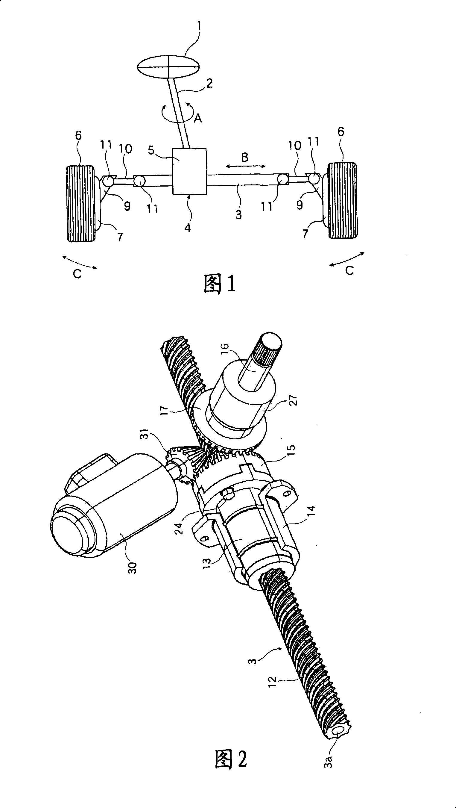
[0044] FIG. 1 shows an example of a steering device to which the present invention is applied. This steering device has: a steering shaft 2 combined with a steering wheel 1, a follower rod 3 that moves axially according to the rotation of the steering shaft 2, and a handle that converts the rotation of the steering shaft 2 into the follower rod 3. A motion conversion device 4 for axial movement; the follower rod 3 runs through the gear box 5 of the motion conversion device 4 . A steering arm 9 is provided on a hub 7 supporting the left and right steering wheels 6 , and both ends of the follower rod 3 are respectively connected to the left and right steering arms 9 via tie rods 10 . In addition, the connection of the steering arm 9 and the tie rod 10 and the connection of the tie rod 10 and the follower rod 3 are performed via a ball joint 11 .

[0045] When...


PUM


Abstract

The present invention provides a steering device capable of being formed in compact size, so that it can be easily applied to even a vehicle with a small engine room such as a front-drive vehicle, and having a novel construction that is not a ball and nut type nor a rack and pinion type, wherein the steering device steers steering wheels by converting rotation of a steering shaft into axial movement of a relay rod. The steering device comprises a gear casing which is penetrated by the relay rod, a spiral ball rolling groove formed in the relay rod in the gear casing so that the magnitude of a lead is 1 or greater, a nut member screwed onto the ball rolling groove in the relay rod with a large number of interposed balls and supported rotatably relative to the gear casing, an input shaft to which the rotation of the steering shaft is transmitted and crossing the relay rod or twisted relative to the relay rod, and a first transmission gear transmitting the rotation of the input shaft to the nut member.

Description

technical field [0001] The present invention relates to a steering device for operating a steering wheel according to the rotation of a steering shaft, and particularly relates to a steering device that can be easily developed on an electric power steering device. Background technique [0002] Conventionally, as a steering device for operating a steering wheel of a vehicle, a product called a ball nut type or a rack and pinion type is known. [0003] The former ball nut type structure is as follows, that is, by converting the rotational motion of the steering shaft applied by the driver into the swing motion of the steering rocker arm, the follower rod connected to the front end of the steering rocker arm is moved axially left and right, The direction of the steered wheels is changed according to the turning amount of the above-mentioned steered shaft. Because a ball nut is used in the process of converting the rotational motion of the steering shaft into the swing motion o...

Claims


Application Information

Patent Timeline
Patent Type & Authority Applications(China)
IPC IPC(8): B62D5/04
CPCB62D3/02B62D5/0421B62D5/0448F16H25/2204F16H2025/2093Y10T74/19749
Inventor 太刀挂雄二
Owner THK CO LTD
Features
  • R&D
  • Intellectual Property
  • Life Sciences
  • Materials
  • Tech Scout
  • Unparalleled Data Quality
  • Higher Quality Content
  • 60% Fewer Hallucinations
Learn More