Mechanical manufacturing clamp

A technology for machine manufacturing and fixtures, applied in the field of machine manufacturing fixtures, can solve problems such as being unable to meet the needs of actual operations, unsuitable for clamping small workpieces, and bulky.

Inactive Publication Date: 2018-08-17
XUZHOU MASTER MECHANICAL TECH CO LTD
View PDF0 Cites 3 Cited by
  • Summary
  • Abstract
  • Description
  • Claims
  • Application Information

AI Technical Summary

Problems solved by technology

[0002] In the process of mechanical manufacturing, many operations need to clamp and move the workpiece, and place the workpiece in a suitable position. The existing clamps are large in size and complicated to operate. They are not suitable for clamping small workpieces and cannot meet the needs of actual operations.

Method used


Image

  • Mechanical manufacturing clamp

Examples


Embodiment Construction

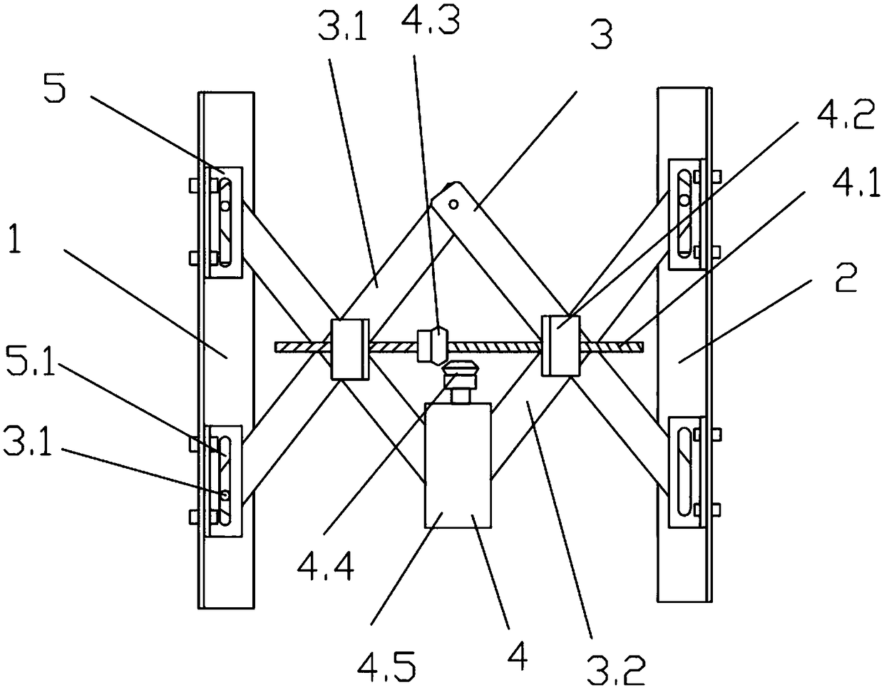
[0010] combined with figure 1 , a mechanical manufacturing jig, including a left splint 1 and a right splint 2 oppositely arranged, the top of the left splint 1 is connected to the top of the right splint 2 through a telescopic assembly 3, and the telescopic assembly 3 is provided with a Telescopic drive assembly 4.

[0011] As a preferred implementation of this embodiment, the telescopic assembly 3 includes several X-shaped articulated rods hinged to each other, and the tops of the left splint 1 and the right splint 2 are provided with sliding parts 5 corresponding to the telescopic assembly. The telescoping assembly 3 is movably connected with the left splint 1 and the right splint 2 through the slider 5 .

[0012] As a preferred implementation of this embodiment, the sliding part 5 is fixedly connected to the top of the left splint 1 and the right splint 2, the middle part of the sliding part 5 is provided with a strip-shaped slideway 5.1, and the end of the telescopic ass...


PUM


Abstract

The invention discloses a mechanical manufacturing clamp. The mechanical manufacturing clamp comprises a left clamping plate and a right clamping plate which are oppositely arranged, wherein the top of the left clamping plate is connected with the top of the right clamping plate through a telescopic assembly; a telescopic drive assembly which is connected with the telescopic assembly is arranged on the telescopic assembly; the telescopic assembly comprises a plurality of X-shaped hinged rods which are hinged with one another; the top of the left clamping plate and the top of the right clampingplate are equipped with a slide part which corresponds to the telescopic assembly; and the telescopic assembly is movably connected with the left clamping plate and the right clamping plate through the slide part. The left clamping plate, the right clamping plate, the telescopic assembly and the telescopic drive assembly are connected in a matched mode, so that the multifunctional manufacturing clamp is simple in structure, is relatively small in size, is convenient to use, can meet clamping workpieces, and meets the needs of practical production.

Description

technical field [0001] The invention relates to the technical field of mechanical manufacturing, in particular to a fixture for mechanical manufacturing. Background technique [0002] In the process of mechanical manufacturing, many operations need to clamp and move the workpiece, and place the workpiece in a suitable position. The existing clamps are large in size and complicated to operate. They are not suitable for clamping small workpieces and cannot meet the needs of actual operations. Contents of the invention [0003] In order to solve the above technical problems, the technical solution provided by the present invention is: a mechanical manufacturing jig, including a left splint and a right splint oppositely arranged, the top of the left splint is connected to the top of the right splint through a telescopic assembly, and the telescopic assembly is provided with There is a telescopic drive assembly connected to the telescopic assembly. [0004] As an improvement, ...

Claims


Application Information

Patent Timeline
Patent Type & Authority Applications(China)
IPC IPC(8): B23Q3/06
CPCB23Q3/06
Inventor 郭楠肖彩
Owner XUZHOU MASTER MECHANICAL TECH CO LTD
Why Eureka
Try Eureka